Designer
-
Posts
1,750 -
Joined
-
Last visited
-
Days Won
175
Content Type
Profiles
Forums
Events
Gallery
Everything posted by Designer
-
Jan, I am not sure about your second question as there may be some terminology issues. The cap goes on top of the mast. The ply piece under the mast is the step and the piece in the mast that fits into the step is the heel. I like to glue in the step last after all of the glass work is done and I like to check that the mast is vertical when the boat is level. The same rules apply to the step for the right clearance as for the collar. If the mast and heel is tight in the step, it is easier to adjust the step in the vise rather than in the boat.
-
Jan, You are fine. The mast in it's relaxed state sits vertical and the mast collar pitches down aft. This is why the mast is tight, you can see a gap at the aft side of the collar. There will be a gap on the underside forward. You just need to ease the forward top and aft underside until the mast slides nicely. I like to use a length of 1 1/2" PVC pipe or something similar to wrap some sandpaper around working it up and down. The trick is to make hole loose enough to allow for epoxy and paint without being sloppy. You do not need to fuss much at this stage as the deck has to go on which may tighten it up more.
-
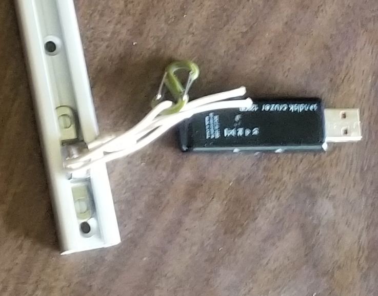
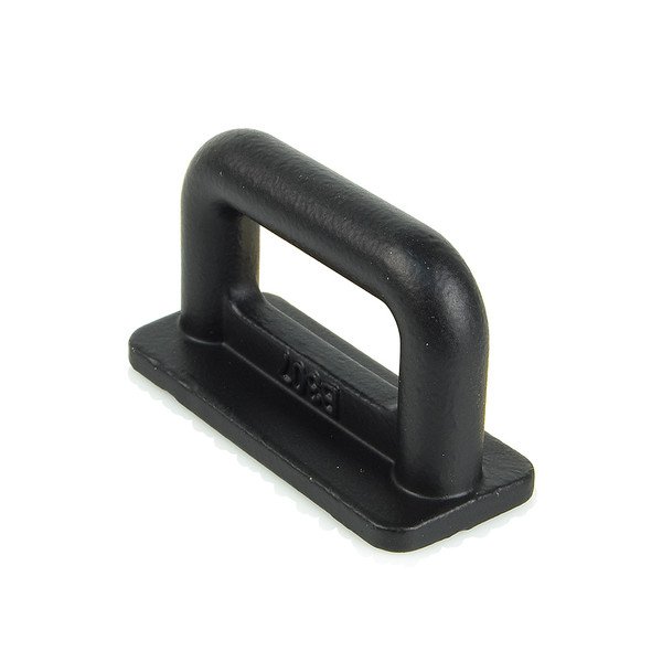
While fiddling with some hardware I discovered that a Harken 073 eyestrap fits and slides surprisingly well in our sail track. I always have a couple of them in my handy repair kit and with a bit of lashing cord I can quickly make a repair and be back on my way if I should ever have a slide or two fail.
-
Sorry about not wrapping this up sooner. My shop built slides tested worst of all even though I had a larger cross section. After I looked up the mechanical properties it was obvious why as it was nowhere near as strong. I was surprised that the slides that come on our sails tested better than the ones that we buy domestically. Who knows where any of this stuff originates from anymore? We then searched the web and found the perfect slide right under our noses. It is a slide made out of stainless steel and coated with teflon for low friction. It looks exactly like our regular slides but black. It is a bit pricey at around $12. I am not going to rush out and change Carlita's slides, as I have said bfore that I have never broken one. On bigger boats like Jays MF246 with larger sails and forces I will use them at the head and tack and at the reef points.
-
Hi Frank, I am glad that you are still enjoying the boat. It was good to see your video of her sailing herself. You do not have any worries with the masts. They are just collars that keep the upper mast sections positioned. The upper section is buried into it's lower partner by about 9" and there is a lower bushing. With free standing masts there is very little mast compression, with most of the forces being side loading the glass epoxy layup can easily handle all the loads that the section can put on it. We bond the bushings because fasteners add potential corrosion in time, plus a slight weakening of the small section where it has it's maximum load. The same reason why we do not to weld them in place as you lose about 30% of the tensile strength from the high temperatures taking the temper out of the high strength aluminum. We know of one set of masts on a CS17 that were welded and as far as I know have not failed. This is because of the happy coincidence that the masts are stronger than they need to be to get the stiffness we want to get the right sail carrying power. It still goes against my grain to weaken a mast by that much. Over time corrosion is our enemy but I am not seeing any in your pictures.
-
Core Sound 15 #162 — Building the “Norma T”
Designer replied to PadrePoint's topic in B & B Yachts Forum
I am responsible for the starboard motor mount recommendation. It is only relevant to motors that do not have reverse gear and transom mounted on 17 mk3's. On the CS15 or any of the CS mk1's you can mount the motor on whichever side that speaks to you. On the mk3 I had to cut the transom down for the exhaust to to clear the transom when rotated for reverse. No, a long shaft does not help as the leg extension is below the exhaust. The problem is that it is such tight fit that I can only fully rotate the motor by turning it to the left. To do this I have to lift the tiller straight up to clear the cockpit coaming, plus the motor tiller is on the left which puts it close to the coaming. If mounted to starboard I could just rotate the motor to port without having to remember to lift the tiller straight up. There are other motor possibilities for the mk3's which we can discuss elsewhere. -
Scott, Yes, same as usual.
-
We started the little Suzuki yesterday for the first time this season and I believe that the Chick method works. I went through the standard starting sequence and gave it about 4 pulls, then Alan gave it a few pulls. He then blew down the fuel fill and she roared into life on the next pull.
-
I too think that Chick might be on to the problem. My Suzuki 2.5 has been the perfect engine except for the first start of a cruise. Once it has been run for a while it starts every time on the first pull. I am not keen on kissing the inside of a fuel cap but I know that I will become desperate enough to do it. I want to start mine soon so I will give it a try. I wonder if I can cobble up a cap with a hose to make it a bit more sanitary. Paul, I am glad that you got out for a sail. Your weather should be getting real pretty now.
-
Inner Banks 130 Sailing Adventure June 14th
Designer replied to AmosSwogger's topic in B & B Yachts Forum
I am lined up to go. I am 25 miles from Potters Marina so I will sail up on the 14th. John worked out a nice cruise. The weather has been crazy this spring so far but there is plenty of opportunity to refine the cruise as the weather dictates. -
Spindrift 12 #1275 - Daggerboard trunk inside finishing
Designer replied to J. Cote's topic in B & B Yachts Forum
Peter gave you good advise. Having built these boats for over 40 years or more, my usual standard was to coat the inside of the trunks on Spindrift's with three coats of resin and call it done . On bigger boats I always glass the inside of the trunk sides before assembly. Alan pointed out a while ago that it maybe quicker to glass the the trunk insides than do three coats. It can never be bad to have better abrasion resistance. So the upshot is that, coating or glassing works, but glassing should be better. The other issue is glass taping the trunk to the bottom. Again this is a complicated issue. It is always better to glass both sides of a joint. The problem is that, as been pointed out, it is hard to taper around the inside of the trunk bottom slot so that you do not narrow it and do not get any bubbles in the glass as it does not like to go around tight corners. I decided that it was too hard for home builders to do well without a lot of pain, so I decided to eliminate the inside corner taping and double up on the fillet and inside taping. I stagger the two layers of 3" tape by 1/2". We ended up with a pretty competitive S10 racing fleet so instead of cutting the bottom slot to the trunk rectangle we cut out the bottom to match the profile of our dagger board to have less turbulence. This would be impossible to tape inside without a lot of work. I have never seen a failure in one that was done this way so far. -
Nidaplast and carbon Spindrift N11 build
Designer replied to ForthBridge's topic in B & B Yachts Forum
This subject keeps coming back. There are many ways to measure strength and one of plywoods greats properties is that being a low density material it's stiffness to tensile strength to weight ratio is close to ideal. For instance, if we were building an aluminium Spindrift and trying to keep it from being too heavy, we could look at 16 gauge which is a cigarette paper thicker than 1/16" or 1.651 mm for our mathematically challenged European friends. Now if we compare it's weight to 6mm okume, it comes out at about twice the weight per square foot or meter. That already is a pound or kilo too far for me to cross already, not to mention that the bottom would probably need stiffening with a couple of stringers, compounding the build by a lot of extra welding. We do not even need to factor in that aluminium does not float. The Gougeon Brothers used to have great display at boat shows.They had every material that you could build a boat out of. Each piece was cantilevered 12" past the edge of the table and was exactly 1" wide and weighed the same. They varied the thickness of each piece so that the weights would be exactly the same. When the same weight was placed on the end of each piece, people were amazed to see how much stiffer wood was compared to the other materials and compared to steel, which we all know is very strong. The only way to beat wood is to lower the density further and that means to use a core material. As we have seen that can work but a little more resin here and there and we have lost the weight battle. A little extra weight is not a big deal in a work boat but in a tender that has to be manhandled a lot in often awkward conditions, it is a big deal. -
Nidaplast and carbon Spindrift N11 build
Designer replied to ForthBridge's topic in B & B Yachts Forum
I have no problem with a few worts. I would rather them than than have nothing. It is the beginning of the learning curve. I also subscribed to their channel because I love to see their Spindrift living and doing what I intended. I have sailed those waters and it is a lot of fun to see what has happened with the yacthing explosion. In 1975 I cleared into Pukhet in the commercial harbor. The chief of police strongly recommended that I not stay in the harbor as thievery was a problem and told me about a good anchorage, there were no marina's. I was the only sailboat in the area. -
Nidaplast and carbon Spindrift N11 build
Designer replied to ForthBridge's topic in B & B Yachts Forum
I will add my 2 cents worth for plywood versus composite materials. I built my first Catspaw stitch and glue in the late Sixties. We could get thick epoxy for gluing but the the only resin available to me was polyester. She was used for full time cruising which meant that she was in the water if we were not under way. By the end of 1970 the glass tape was de-bonding from the ply even though I used isothalic no wax laminating resin which bonds better that orthothalic resins. I cross hatched the bonding area with a piece of saw blade and primed the wood before laminating. She even got marine borers and had to row with our feet over the borer holes or we would have a tiny fountain. I did the obvious thing and built a masonite female mold and laid up a fiberglass hull. I stiffened the bottom and gunwales with foam. She was a bit shorter to save weight but she came out heavier. It solved the problem with water but it was not as tough as her wood predecessor. While the glass boat was better against sharp objects, she could not take hard use and abuse as well as the wood version like getting crushed at the dock etc.. By 1980 she getting tired and looked like a patchwork quilt from repairs so I decided to build a new 4mm okume plywood Catspaw but with epoxy this time. She was much better than her fiberglass sister and served me well, became the boatyard work dinghy after I quit full time cruising. Around 2005 a friend borrowed her and lost her in a hurricane. She was no great loss as the ply was getting soft. She was not sheathed and spent all of her life in the weather. Don't get me wrong, I love composites and will use them in a flash if I think that it will be better. I like to see experimenting. Plywood has the advantage that it is cheap, user friendly, light and tough. I sincerely hope that you can hand your carbon Spindrift down through generations but only time will tell. Here is a picture of a Spindrift 9 nesting, working hard for her owners. They are about two thirds of their way around the world and I suspect that after they finish, their Spindrift will be ready for another lap with a just a modest refresh. https://sailwiththeflo.wordpress.com/our-dinghy/
-
I have gotten pretty intimate with the 5.80 plans recently so I will attempt to answer these questions. I have seen and created all or some of the above suggestions but I think that Don has struck the right balance for this boat. It not a gunkholer and never will be. It is a no compromise deep water boat. The keel profile is a heavy steel plate that also has the bulb profile. There is a heavy steel flange curved to the hull rocker which he wants welded by a certified welder (there is so much weld length that I would be very confident of my welding). This flange is bolted with 5 pairs of bolts through 5 heavy oak floors. The lead bulb is made in two halves with three large bolts bolting the three parts together. The bolt holes in the lead are counter bored for the heads and nuts, and faired with a soft filler so that it can be dug out. The idea is to have a simple strong structure that is the ultimate in simplicity, strong, reliable with the maximum righting moment for the weight and not interfere with the limited interior. It can be trailed but needs to have a deep ramp to launch. I have trailed a J22 which was possible but restricting. The keel can be all easily unbolted and man handled if necessary, say to get it into a container or long term storage.
-
Core Sound 15 #162 — Building the “Norma T”
Designer replied to PadrePoint's topic in B & B Yachts Forum
On looking a little closer I see that the 3/4" x 1" cleat that tops the side bulkheads is not installed yet. it connects the side bulkhead to the seat. -
Core Sound 15 #162 — Building the “Norma T”
Designer replied to PadrePoint's topic in B & B Yachts Forum
You are still going at an incredible pace and with very nice results. I see that everything is done for installing the seat tops real soon but I see one omission that I hope that you just have not gotten around to yet and that is the cleats on the forward bulkhead and the transom. They support the ends of the seat tops and go between the side stringers and the side tanks. -
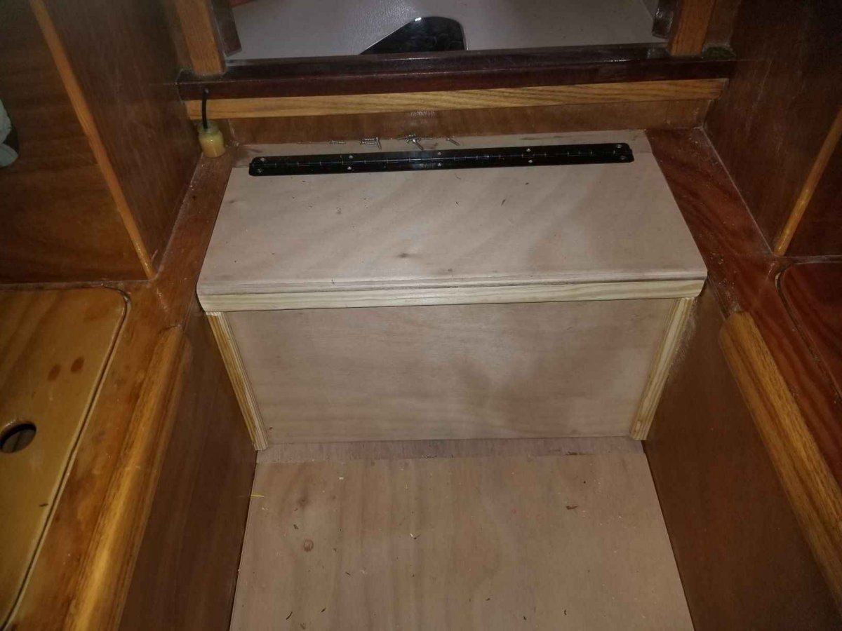
It is interesting that I am finishing up installing a fuel tank under the cockpit and moving the battery forward on the Original OB20 hull #1 that Chick built. The reason is because I bought an almost new Etech 50 that sat around for 10 years and have finally installed it. Remember that after this version the bottom was redesigned with more volume aft for bigger engines so that my need to get weight further forward is relevant to to just this boat. The old fuel tank was about 15 gallons set on the port side back to the transom. I cut a big hole in the cockpit and put in a FT35 35 gallon tank set against the pilot house bulkhead. I hate the idea of burying the fuel tank forever but I wanted the keep the cockpit watertight. I hope that I never get a wave into the cockpit but I want to be able to hose out the cockpit or what if debris clogged the cockpit drains and it rained a lot etc.. I installed the tank with the fuel gauge fuel pickup and filler forward and made a rabbeted kidney shape hatch rabbeted to take 6mm lexan cover which I will set in mastic that I can pry out to access the hardware, like replace the fuel gauge sender or clean out the tank. I do not have access to the tank vent as it is at the other end of the tank but I have the exact dimensions so that I could put in a 4" diameter lexan hatch if the need ever arises but I doubt that will happen. With the fuel pickup forward, the engine will quit if I am on plane before I use the last few gallons, this might not be a bad idea as I will have somewhere between 5 - 10 mile range at displacement speed to get me somewhere if I am stupid enough to run her out of gas. I put the battery on the forward side of the bulkhead with a lift up step to give me instant access to the battery. As the battery (group 31) is heavy and the space is too tight to lift straight up, I put a sliding front that lifts up so that I have more room to work inside the compartment. The battery is held by a screw down base and the wood bar across the top locks the battery down and the screw through the starboard cleat holds the bar in place. The three way battery switch is over kill but it is one that I had. I put her in the water yesterday and she trims out well.


-
Spindrift 12 #1275 - foot hold while sailing
Designer replied to J. Cote's topic in B & B Yachts Forum
I adjusted an eyestrap to fit the bolts of the lower rudder gudgeon and fastened an eyestrap to the aft end of the trunk about 3" up from the bottom. I put grommets in some 2" webbing. I used some 1/8" cord to connect at each end and used the cord to adjust the tension to suit. -
I am sure that the new Marissa will have a happy owner. Thanks for all or your posts, you do not realize how important it is get good feedback so that we can continue to create, especially someone with your level of craftmanship and to see you add your own interpretation to our designs.
-
Spindrift 12 #1275 - Attaching Gunwales at the bow
Designer replied to J. Cote's topic in B & B Yachts Forum
We always strive to make our kits as good as we can and any constructive criticism is very welcome. Without feedback it is hard to improve. The fact that we design and use and cut our kits we can very easily make changes. One of the problems is like with the daggerboard change. Finding and fixing the instructions which can go back many iterations to avoid confusion. -
Spindrift 12 #1275 - Attaching Gunwales at the bow
Designer replied to J. Cote's topic in B & B Yachts Forum
I would call it smart rather than cowardice. If in doubt check it out. I often see builders misinterpret and go down the wrong hole and make it difficult to dig back out. I see that we missed the fore deck beam. Unfortunately, you are the guinea pig as this is the new updated kit. You are correct, follow your directions. Your other question about the daggerboard. That is a new refinement by Alan and I believe that he intended that there be no extra handle, just clean up the hand hole so that it is comfortable. -
Spindrift 12 #1275 - Attaching Gunwales at the bow
Designer replied to J. Cote's topic in B & B Yachts Forum
Jan I am sorry about the confusion. The S12 is the only Spindrift that has no breasthook. You do need an anchor point to attach the forward end of the gunwales and that is the mast collar. It runs through the forward bulkhead to the bow and doubles as a king plank supporting the foredeck and needs to be installed before the gunwales so that you have something solid for the gunwales anchor screw. You do need to install the forward bulkhead deck beam before the mast collar. The reason the above mentioned Spindrifts had laminated gunwales is that they nested. If they were not laminated the gunwales would have straightened out when the boat was cut in halves. You do not need to laminate the gunwales as your boat will not be cut. Having said that, there is a lot of stress on the wood and boat as it is forced in place and they can break if there is a lot of grain run out or some other defect. The advantage of laminating is first, reducing a lot of stress and second, it is unlikely that you will have the same grain defect in the same place in the laminations, You need to take care to sort through the laminations and end for end every other piece if they come from the board. Because you will not be cutting your boat there is no reason to do three laminations. Two will be easier to do and the forces will be reduced to about a third. Whenever I put on gunwales I always study the grain of each piece and put the straightest grain forward where there is the most bend. It is important to install both sides at the same time on the boat to keep it twist free but you may put on one lamination at a time. You could apply glue to one side and bend the unglued partner at the same time so that the bending stress on the boat is equal while the first side is curing. Remove the unglued gunwale later and glue it on. The advantage is that if you you do not have enough clamps you can put most of them on the gunwale being glued and it is easier when short handed. I always pre-fit the gunwales and drill and install the anchor screw as it is easier to get it right without the glue making everything slippery and you are not burning up your curing window of the epoxy and keeping your tools clean. -
Core Sound 15 #162 — Building the “Norma T”
Designer replied to PadrePoint's topic in B & B Yachts Forum
You are making great progress and I see that you are getting some character building as well. Not that I am suggesting you need any more. You have the right spirit for this group, when plan A does not work, there are another 25 letters in the alphabet. I am glad that you are having a well deserved rest tonight because I suggest that you do not tape the inside of the boat until the transom is fitted. This is because the stern shape will change with the transom in place. If you look at the keel where it will meet the transom, there is a small gap. If you look at the keel rocker from the side you will see the keel curving up until about a foot from the stern where the curve starts to bend down. You need to put a prop from the floor to lift the bottom at the aft end of the keel line until it is tight. Then position the assembled transom in it's place assuming that you have trimmed the inwales and side stringers. The transom will force the bottom and sides into their correct shape. It would be a pity to lock the chine and keel into the wrong shape. This does not mean that you have to fit the transom in permanently, you can still take it out again if that suits but you do need it in place when epoxy is curing in the stern area. Keep up the good work but don't get too far ahead, you are putting us to shame. -
Spindrift 12 #1275 - Bay & Bow storage & deck plates
Designer replied to J. Cote's topic in B & B Yachts Forum
You have been given good advise, especially regarding the need to stow and have ready access to stuff. If you will do much sailing it is not a matter of, if you will capsize but when. Remember that during a capsize, everything not stowed or tied down will be gone. Follow Joe's advise about practice capsizing but look at his capsize video first. The Spindrift is an excellent boat for recovery so you are off to a good start. Make sure that your bailer is tied in with enough length so that it can be used without having to untie it. A gallon bleach bottle with the bottom cut off at an angle is about as good as any. I have not had personal experience with that hatch but I have had too much experience with other brands of similar hatches and they all leaked. That is what forced me to create a better mousetrap and design our now standard cockpit hatches. They are a lot of work for a Spindrift, I would use the 8" hatches that Alan suggested and put them on the vertical faces. If you choose the screw in type, I would make a 3/4" plywood spanner to undo them as they can be hard to undo if you tighten them so that they will not leak. Drill a hole in it so that it can be tied in. I once sailed the Small Reach Regatta in my 12' Amanda which has the same cockpit as the Spindrift. I had the same screw in plastic hatches in her and I was able to stow everything that they required to meet their safety rules as well as a set of dry warm clothes and food. A compass was mounted to the trunk and the ground tackle was also lashed to the trunk and oars too. It worked great.