Peter HK
-
Posts
619 -
Joined
-
Last visited
-
Days Won
29
Content Type
Profiles
Forums
Events
Everything posted by Peter HK
-
I don't think this is correct. If you imagine a rigged-per-plan CS17 running square with the mizzen eased out perpendicular to the centreline then the minimum length of sheet needed is double the length from the attachment on the transom to the clew and twice the length from transom to the cleats near the aft bulkhead. As the foot of the sail and the distance from mizzen mast to transom are both about 7ft, by Pythagorean theorem the transom to clew length is the square root of 7 squared times 2, ie 49 +49 = 98... close enough to 100, the square root of which is 10ft. Thus total sheet length is 10x2 plus 2x2 equals 24 ft. By the same estimation, the length of a mizzen sheet led to the centre thwart is 20 ft plus the length of the boom plus the length of the descending part from the block on the mast to the cleat. This is approximately 20 ft plus 7 ft plus 5 ft equals 32 ft. Of course extra is needed for tails and easing the boom forward of the beam but this is the same for both systems. Cheers Peter HK
-
My plans (from 2006) listed mainsheet at 42 ft and mizzen at 35 ft...I doubt they have changed. I've used 8 mm for the main and it works well. For the mizzen, as I've rigged it to lead along the boom and down to a swiveling cleat on the thwart, I've changed to 6mm as the smaller line seems to run through the blocks more freely and the tensions are so low the 6mm line doesn't worry my hands. I suppose 8mm and larger blocks would probably work nearly as well, if you find handling a 6mm line a problem. If you rig as per plans with the mizzen sheet double ended to aft cleats the 8 mm will be fine. Good luck on the launch Cheers Peter HK
-
I built my CS17 in a garage approximately 19ft long and 8 ft wide....20x16 for a CS15 is luxury Cheers Peter HK

-
Don't worry, regarding mast rotation you can do either - that is fix it or let it rotate. There has been some discussion of this over the last few years with advocates of either persuasion, so I'll give my interpretation. Rotating the mast results in slightly better flow over the sail. I chose to not allow rotation as I feel the halyard and reefing lines (if you have them) work better if kept aligned and I feel this is more important for the sailing that I do on a CS17 (cruising rather than racing). The snotter tension issue depends on how long a line and how stretchy it is- if you had hi tech, minimal stretch braid and not much length (eg only a couple of feet as if it is cleated on the boom) then when you ease the sail the tensions can get very high. With the main led aft there is lots of line to provide a bit of stretch. I wouldn't run the snotter along the mizzen boom for this reason and also it's so nice to be able to adjust it while sailing. Run it down to a cleat (of any sort ) on the front of the mizzen mast to a convenient height and use simple polyester line to allow a bit of stretch. You can see the snotter line cleated on the front of the mizzen mast in this photo. Cheers Peter HK

-
Doug Cameron said Could I ask you to clarify this statement, as terminology varies a little around the world. To me, here in Australia, a pad eye generally means a larger square, round or oblong fitting with at least 4 attachment holes. A simple 2 attachment stainless fitting is generally called a saddle. I believe eye strap is often used to describe the same double attachment fitting in the US. As I have a pad eye, bent to match the curve of the mast with 4 attachment points, I'd like to know if we are talking about the same thing and if it is likely to fail. It wraps around the mast a little more than a quarter diameter so takes a lot of the force in shear on 2 of the 4 screws. Did you mean a fitting with 2 attachments? Thanks Peter HK
-
Rivets have their own problems. Aluminium rivets are relatively weak, stainless or monel rivets have electrolysis problems which limit their lifespan, rivnuts are very good but expensive. In general though these fasteners (and screws) are best when subjected to shear forces rather than tension. Having something that wraps around the mast with a few attachments in different planes is ideal. Will a couple of rivets in tension hold adequately? Depends on how hard you push it and how much corrosion. If it fails, it will be at the worst time...when being really stressed. Also as size goes up so does stress on each element of the boat, often exponentially. What works on a spindrift may not work on a larger boat. Cheers Peter HK
-
I also didn't trust a simple saddle (eye strap) so I found a largish pad eye with 4 screw holes and about 50 mm square. I bent the base plate to match the curve of the mast and screwed into the mast. As my lower section is 3mm thick and the curve of the baseplate shifted some of the force into shear and there were 4 screws I felt this was adequate. Here's a photo where you can see half of the baseplate on the front of the mast- the curve is visible. Of course if you want a really unbreakable option you could go for something like this. https://www.whitwort...tAbsolutePage=1 Cheers Peter HK

-
Hi Dig I agree it's best to PM me when you have a plan. I haven't met Dee Cee or seen his boat as yet but he's in the Wooden Boat Association of Queensland, and as my brother is editor of the newsletter I could probably get some contact details if he doesn't see this on the forum. Cheers Peter HK
-
Hi Dig I'm in Brisbane with a CS17 if you are planning a trip. Cheers Peter HK
-
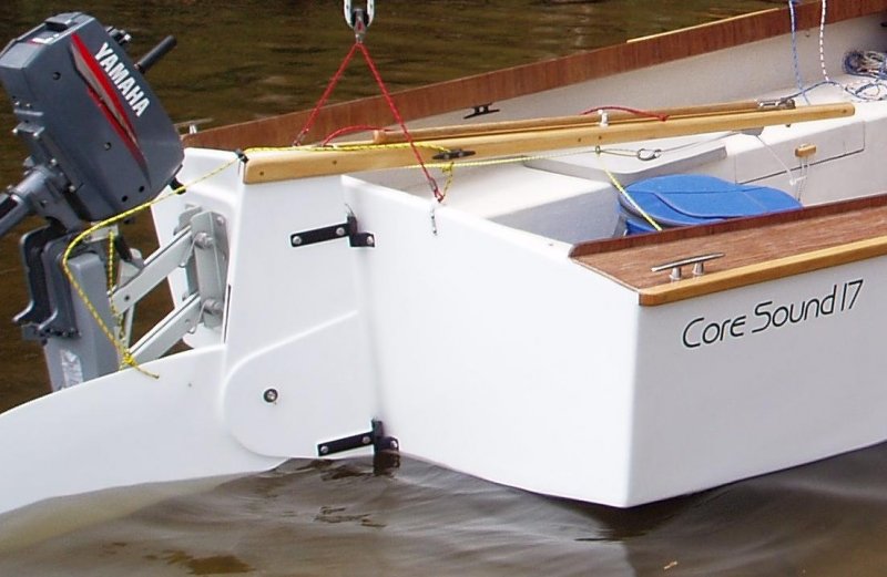
Here's a photo of mine - the red line is the standard downhaul and the yellow line the uphaul which I take to the small horn cleat. Cheers Peter HK
-
Hot is better than cold for epoxy- there are slow hardeners for summer and you can keep building in winter. Here in Brisbane is like Florida in temperature terms. Learning how thick to make the epoxy for the differents jobs etc is all part of the skill. Fillets can be made very neatly, especially with wet on wet glass tape and a brush. In terms of time though it always take 2-3 times longer than you think it might at the beginning. Good luck Peter HK
-
I'll give you my experience, it may help. I had sailed for many years on racing dinghies, small catamarans, then as crew are larger offshore boats (initially monos then multihulls) and finally bought a series of larger boats myself including a Farrier F31, then a Chamberlain 34 ft tri, and finally a cruising catamaran. I used to pay other people to repair the inevitable damage of hard racing (dismastings etc) and marveled at how they could fix timber and fibreglass so you could hardly tell. One time I inherited an 8 ft fibreglass tender with ply thwarts that had rotted out and thought I would have a go at repairing it in the garage at home. I read a few books, bought some ply and epoxy and glass and fixed it. The first time I rowed over to another yacht the skipper said "what a nice dinghy". I was amazed at how quickly I learnt to use epoxy/fillet/glass....the first few attempts were ugly but the learning curve was fast and by the time I'd finished that job (maybe 20 hours) I was reasonably proficient. I also realised I enjoyed the task and decided to build from scratch. I selected a John Welsford design (Golden Bay Dinghy), shortened it a little to 11.5 ft and started building. That boat took me 170 hours to complete and would be about the same amount of work as a spindrift 12. Since then I've built a few more...a kayak, a Bolger 30 ft folding schooner, a CS17 and I'm midway through a nesting catspaw. If I built the Golden Bay dinghy again, now, I'd probably knock off 40-50 hours from the build time as one learns to be more efficient. Anyone can build a boat, the techniques are easy to acquire, it's satisfying and the only really important thing is persistence. Make sure the first few epoxy fillets and bits of glass are in places that will be well hidden in the end (or do a few practice ones first) Cheers Peter HK
-
I once went to the trouble of attempting to plot a polar diagram on my CS17. This was only a single set of measurements on a day with a steady 6-8 knots of breeze and even the slight variations with gusts/lulls made the curve a bit uneven. An accurate polar diagram would need many more data points to be very reliable. Nevertheless the results were interesting. The optimal VMG to windward was 50 degrees...I could point higher but speed dropped off; sailing lower gained speed but not enough to make up for the extra distance. HTH Cheers Peter HK
-

Sailing with the main in the center or single step position
Peter HK replied to sitearch's topic in B & B Yachts Forum
I'll throw in my 2c worth. I didn't put in the third mast position when building as I intended from the beginning to have an effective reefing system. I can easily reef my main from the cockpit. Here in Australia we also quite often have strong breezes so I asked the sailmaker to put in 2 reefs in each sail. From his computer my total sail area is 139 sq ft- 76 in the main and 63 in the mizzen. With 2 reefs in each sail these figures are 34 sq ft and 28 sq ft respectively for a total of 62 sq ft ie just less than the full mizzen area. The big difference however is that the centre of effort of the double reefed cat ketch is nearly 2 ft lower than the same area in the full mizzen...this means the same drive with significantly less heeling force. I feel this is a better arrangement, especially as with the cat ketch rig you can still heave to and drive the boat through tacks if the waves are making that difficult. Of course if running downwind in a gale then the mizzen can be dropped and that leaves only the double reefed main. Bare poles is the last resort Cheers Peter HK -
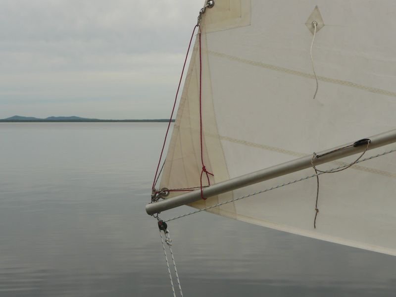
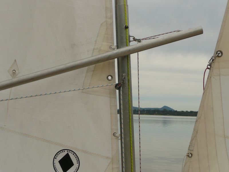
You can also rig the mizzen sheet with a turning block on the mast and so overcome any downward tension on the boom. The 2 photos below show the aft and forward ends of the mizzen sprit boom (not shown in either is the fairlead for the sheet at about the halfway point to keep it tidy). Cheers Peter HK
-
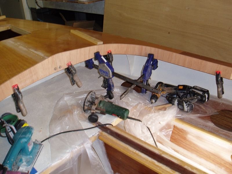
If you are not concerned with grain orientation, eg if you are going to paint, then orienting the ply so that the 3 of 5 veneers have the grain vertical and only 2 veneers have a horizontal grain means that it bends much more easily. I didn't need heat or soaking at all. I used simple butt joins but added a second strip of ply on the outside of the coaming above deck level to give it a more durable and comfortable half inch edge and staggered the butt joins. Cheers Peter HK

-
Excellent article on downwind sail trim for Cat Ketches
Peter HK replied to rattus's topic in B & B Yachts Forum
I once went to the trouble of doing a set of figures for a polar diagram for my CS 17, armed with a compass and GPS. The limitations are obvious as this was only one set of figures in about 6-8 knots of breeze which was mostly steady but clearly there would have been some fluctuation in wind strength as I was changing courses. To get any real accuracy this would need to be done a few more times and averaged. It wouldn't necessarily apply in stronger breezes. Nevertheless the figures showed an optimal run angle of 150 degrees- at that angle I was sailing 19% faster than square on a course 15% longer. At 140 degrees I was sailing 30% faster than dead square on a course that was 30% longer i.e. no net gain. 160-170 degrees was no faster than square. Best VMG to windward was at 50 degrees. Cheers Peter HK -
Excellent article on downwind sail trim for Cat Ketches
Peter HK replied to rattus's topic in B & B Yachts Forum
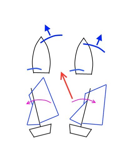
John I think this image from the article is the explanation you want. As you can see the force of the sail (blue arrow) is not directly forward but a little to the side when fully eased and a little the other way when trimmed in. The force can be considered as a combination of a forward component and a small sideways component. As this force is acting through the CE of the sail, nearly halfway up the mast, these sideways forces will heel the boat one way, or the other, depending on trim. HTH Cheers Peter HK
-
Here's a photo of where it landed on mine. Cheers Peter HK

-
Where's the photographic evidence? Peter HK
-
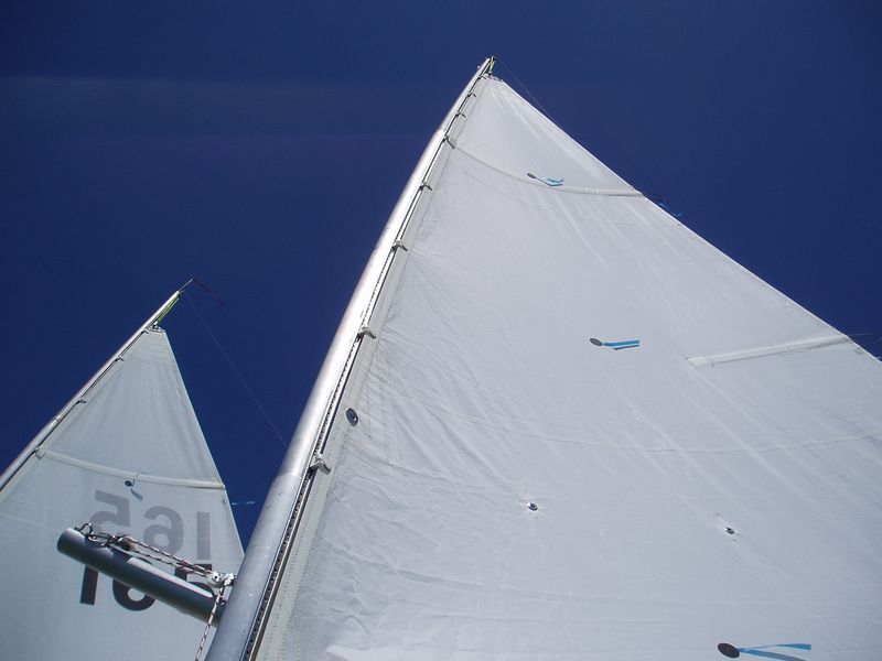
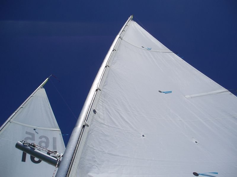
Hi Edward I'll give an answer based on an educated guess and your plan reproduction. My plans from 2006 only suggested a wood or fibreglass topmast on a 2 part aluminium lower mast. I see that a 2 inch aluminium topmast is now an option. I see from your plans a wooden plug is fitted into the top end- presumably to make the mast semi watertight (which is good in a capsize as the buoyancy of the masts is important (though not enough). I suggest you just put in a good wooden plug, with enough bury, in the top end. I made my masts a bit longer (8-10 inches) as there were many comments that people wanted to raise the sails a bit higher on a calm day and needed room to fit halyards. In the end I could chop 6 inches off mine and it wouldn't hurt but they are doing no significant damage being a bit long- see photo but note the topmasts are wood painted to look like aluminium. I believe the closet rod comment was from the non track version of the masts (at least it was on mine) and wouldn't worry about that. As long as the masts are long enough with a good wooden plug there should be no problems, without worrying about a few inches here or there. Cheers Peter HK
-
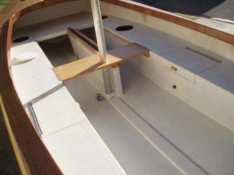
Here are a couple of photos Cheers Peter HK

-
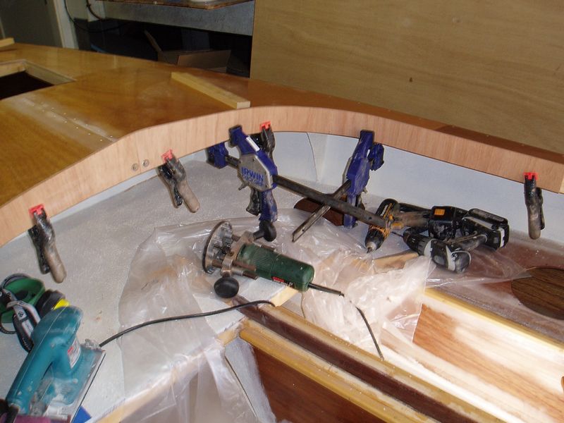
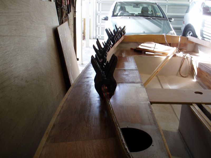
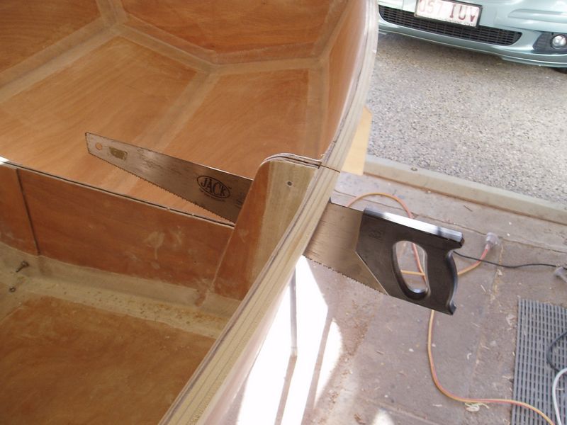
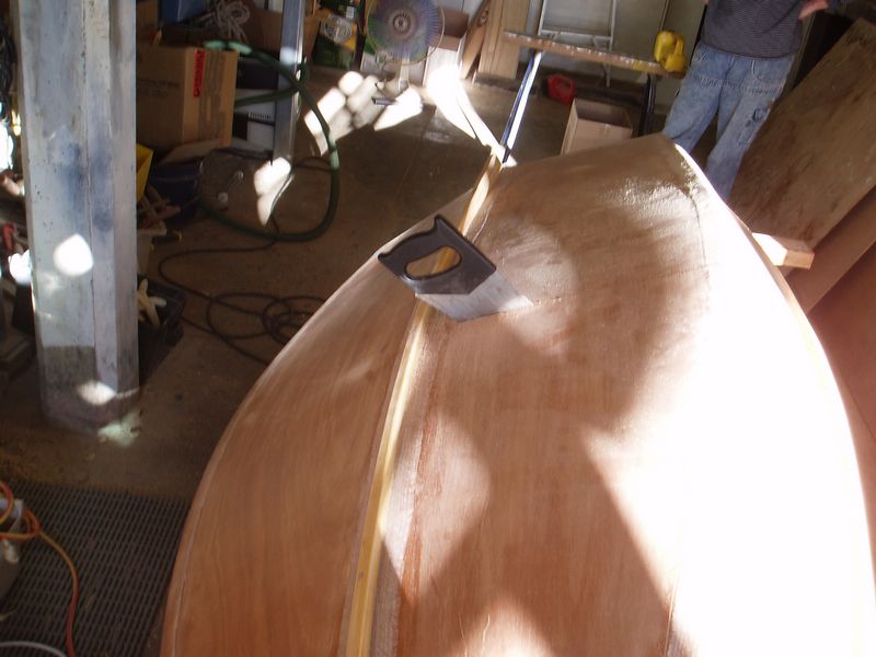
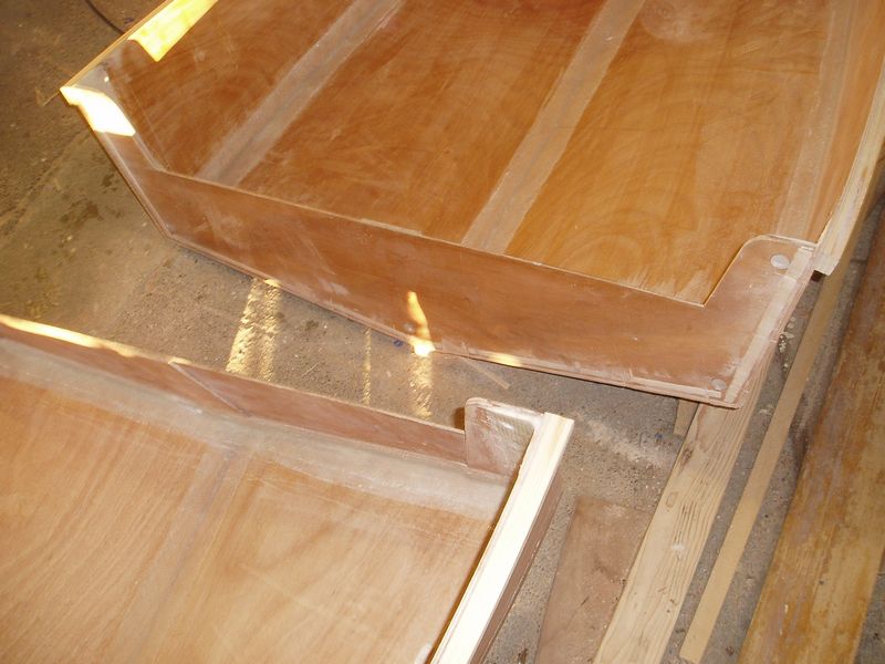
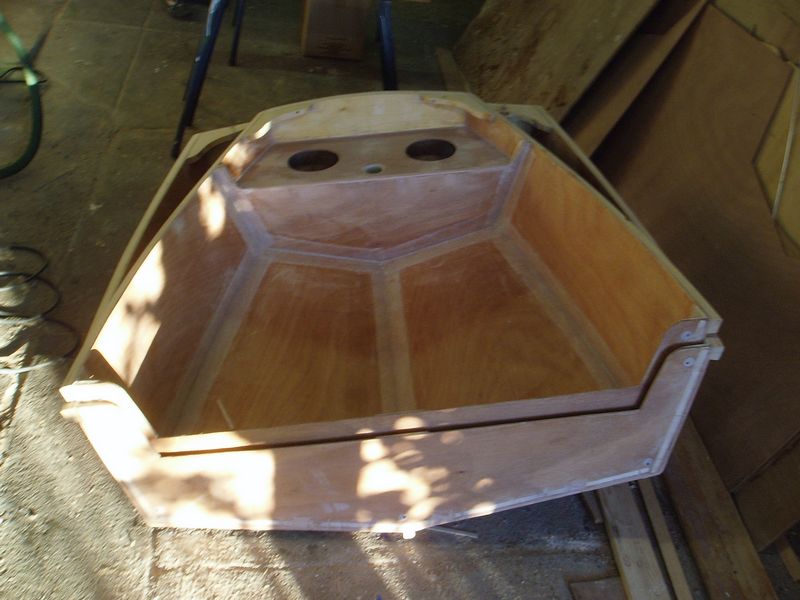
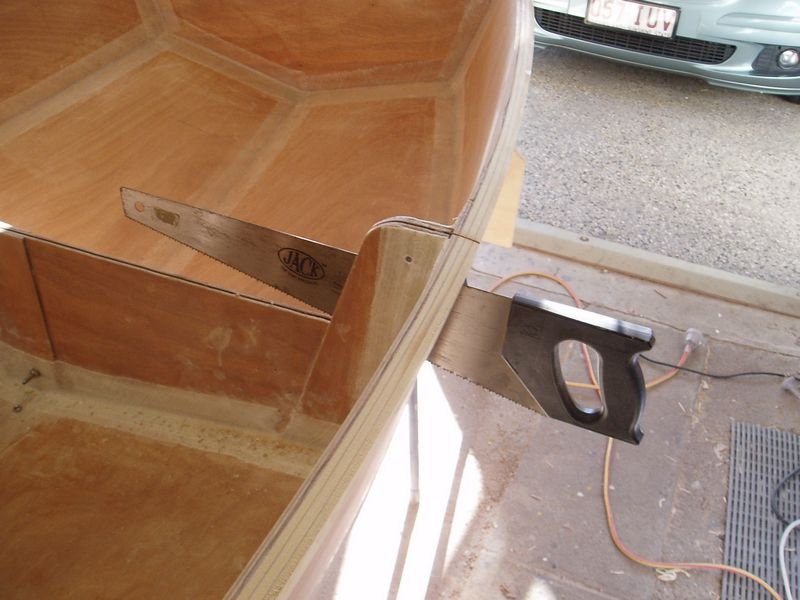
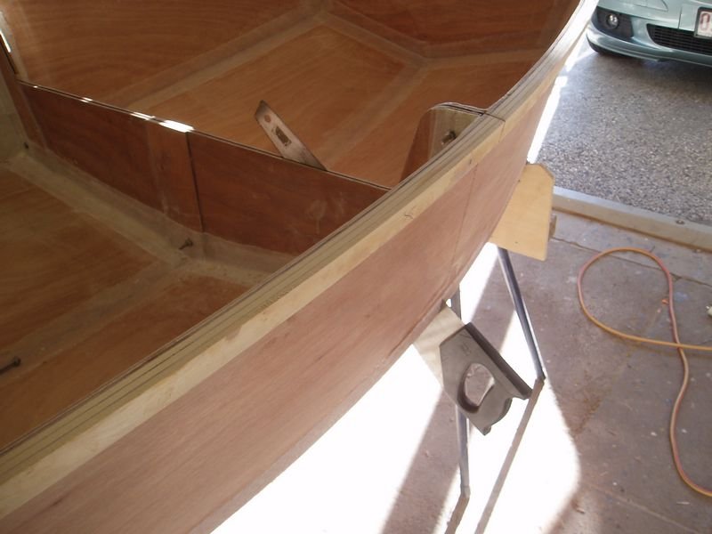
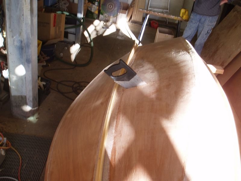
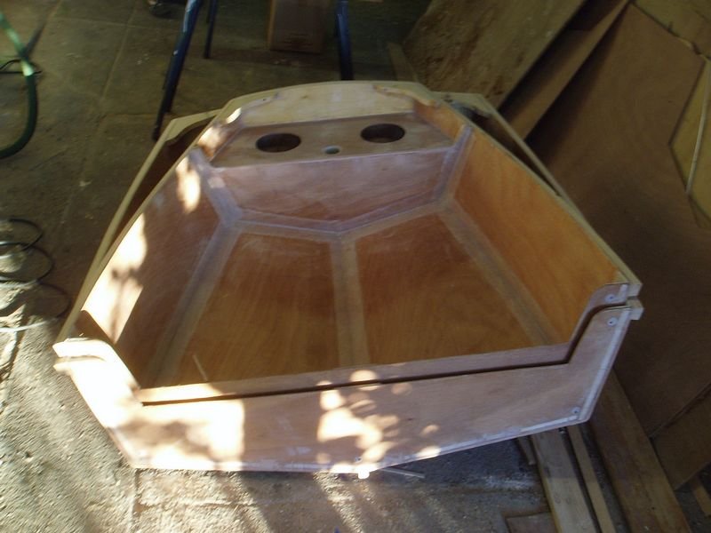
Well today I made the big transverse incision. It didn't go perfectly. I started well and cut through the gunwale and down the topside quite nicely. I reattached the top bolt and continued the cut around the chine. I continued along the bottom for a short distance. Then I ran into a problem...the standard saw wanted to cut out through the ply bulkhead and I couldn't get the Japanese pull saw to work either as it jammed, presumably due to the minimal set. At this point I started to work on a different principle, unfortunately forgetting to photograph it. I decided to establish some pilot holes to draw a line to cut to. This took a little trial and error but wasn't too hard. I then used the jigsaw to do the cut...It was fast, easy and accurate. If I were doing this again I would drill pilot holes before fitting the double bulkhead and use a jigsaw except at the gunwales and chines. It worked out OK...I have a 3 inch section of bulkhead to repair but that won't take long. One other thing- I used balsa strips as the spacer and they worked very well, easy to cut and remove but very accurate in separating the bulkheads. Cheers Peter HK



-
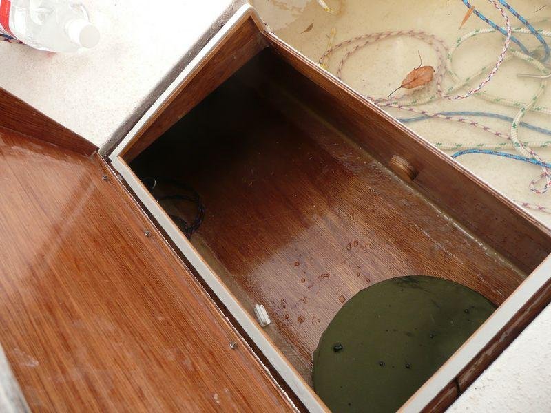
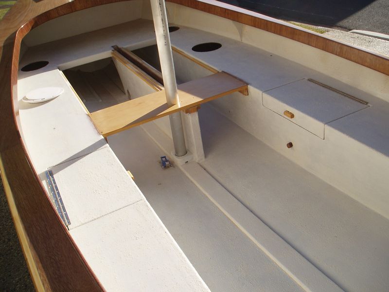
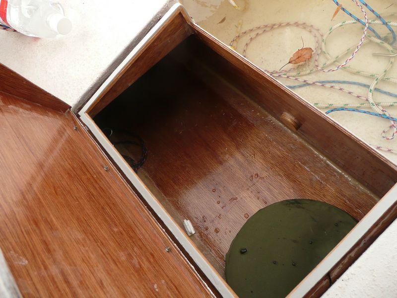
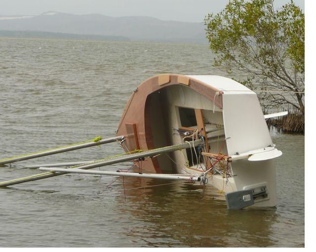
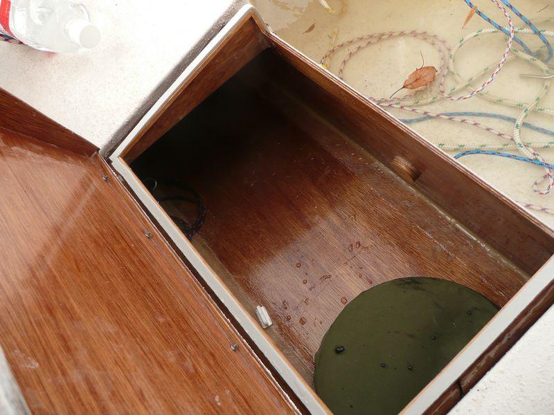
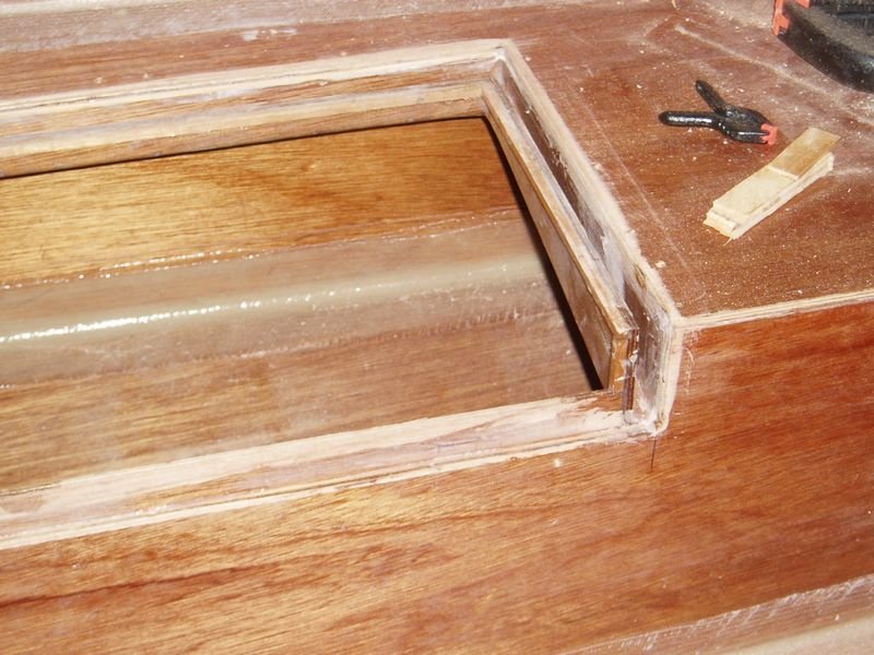
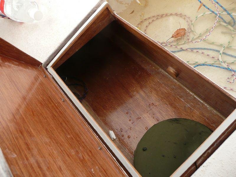
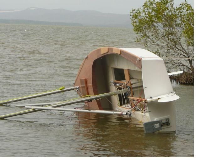
The previous post has a good link to doing the hatches. I did them slightly differently by lowering the front face and running the seal around that- this allows easier access through a slightly larger hatch entry. As to how watertight they are- I've never had a drop in the tanks from waves/spray and I know a hose won't get through. Capsize is a little different as the pressure from waves can overcome the low pressure seal and let in a few drops as shown in the above photo. That was after my capsize test when the hatch was under water for a minute or two. The total amount of water was about 5 ml. They are very nearly completely watertight. Here's a photo of the capsize waterline showing the outboard edge of the hatch completely submerged. Cheers Peter HK
-
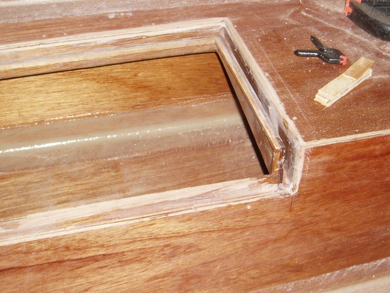
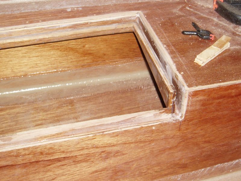
Hi Edward I'll add another variation on hatches. I made mine with a larger entry by lowering the front face an inch or 2. This is common practice on production boats to allow ease of access. What this means is that you have to run the seal around the front of the gutters and across the front of the recessed ply face at the lower part of the vertical part of the hatch seat. This means you don't have to cut out the stringer in the hatch lid except for an inch at the ends. As long as there is a reasonable ring frame you can have a larger hatch. It certainly is as watertight as these hatches can be, as evidenced by the photo below after a capsize test. Hope that makes sense. Cheers Peter HK