Pete McCrary
-
Posts
692 -
Joined
-
Last visited
-
Days Won
40
Content Type
Profiles
Forums
Events
Everything posted by Pete McCrary
-
QUESTION: I wonder if an Anderson Bailer installed reversed with the flapper removed -- and the boat moving (by wind or motor) at about 4 knots -- would that [motion] create enough "head" to completely fill the tank and, perhaps, overfill it into the footwell ?? In the ordinary position it apparently creates enough negative head (- 9 inches of water) to suck water completely out of the ballast and into in infinite pool 9 inches higher. Anyone know the answer? Maybe no pump is needed. Doesn't "pitot tube" move a pointer (or a column of fluid) by moving thru a fluid?
-
Chick, While inverted did you install the Anderson bailers? And, I assume, the CB was installed with its pennant reeved up thru the CB trunk. Right?
-

Core Sound 20 Mk 3 -- #4 "Chessie" . .
Pete McCrary replied to Pete McCrary's topic in B & B Yachts Forum
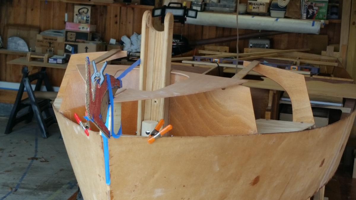
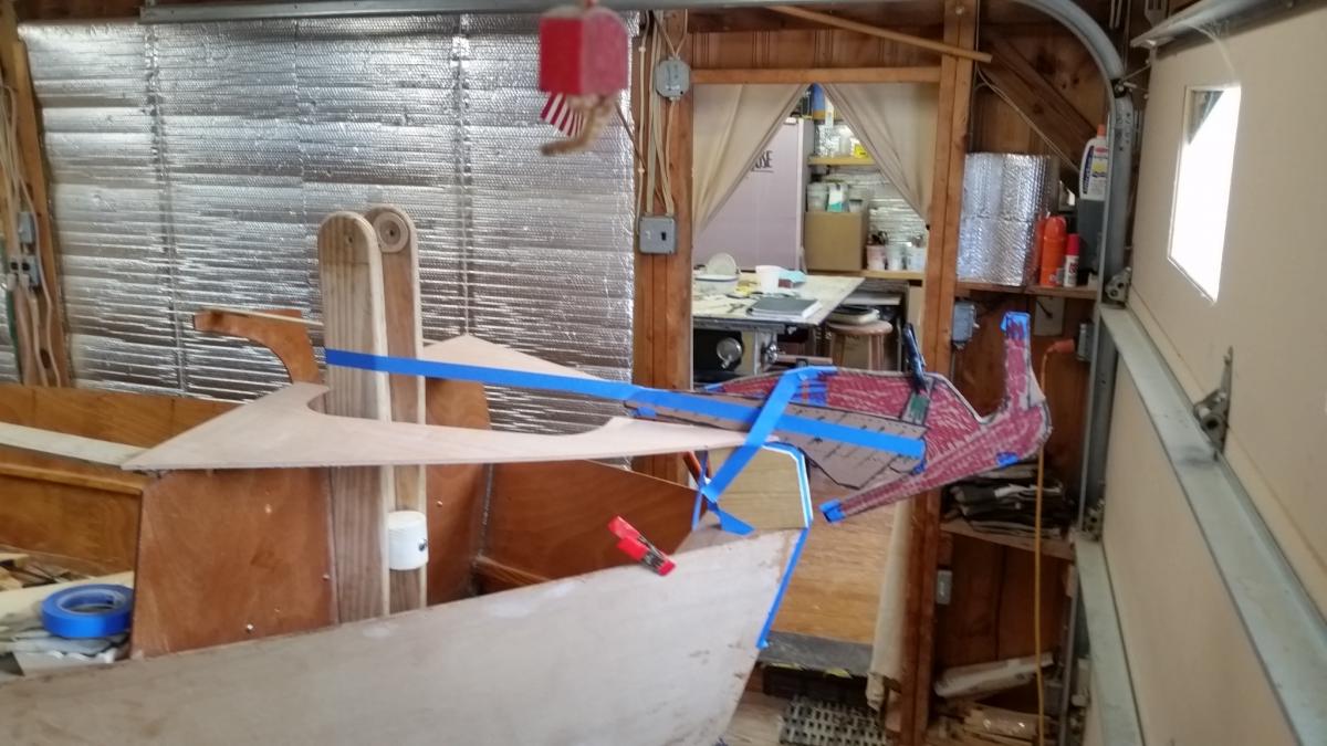
It's all OK. The anchor mockup was just to see if the hardware I ordered would fit. Now that I understand what the bow actually looks like -- the anchor will be held just a little further away from the stem. I'm a little concerned about the weight (so high and far forward) of the anchor (9.8 lbs) and the roller assembly (8.5 lbs) -- but since I nearly always sail solo, it shouldn't be a problem. The sheer strakes are in place almost ready for spot welding. I'm really impressed with the accuracy of these very long pieces. They fit so nicely. Getting the angle right. Next, before tac welding, I think I'll wire up the hanging knees.


-
Core Sound 20 Mk 3 -- #4 "Chessie" . .
Pete McCrary replied to Pete McCrary's topic in B & B Yachts Forum
Alan,... Great record performance in the Ultimate Florida Challenge. To do that you had to be in terrific physical and mental shape. Gongratulations !! The sheer strakes are wired [together] at the stem and nestled into the "lip" of the 1x 2 boat-length batton suggested by Graham. That back-screwed batton has set the inside beam measurements right at the dimensions you gave me earlier at the hanging knee positions. Blks 1, 2, 3 (in-place temporily), and 4 brackets aft set at 72.5 dgrs (2 ea P/S) have the sheer strakes at the required angle and very nicely set. The computer-drawn lines on the inboard side of the sheer strakes lineup VERY close (i.e., within a "line width or two") to the bulkhead positions. Amazing accuracy! Haven't tac welded yet. It all needs just a little fine tuning with wires, wedges, etc. When you get a chance -- check out my last few posts. Really glad you're back safe and sound. -
Core Sound 20 Mk 3 -- #4 "Chessie" . .
Pete McCrary replied to Pete McCrary's topic in B & B Yachts Forum
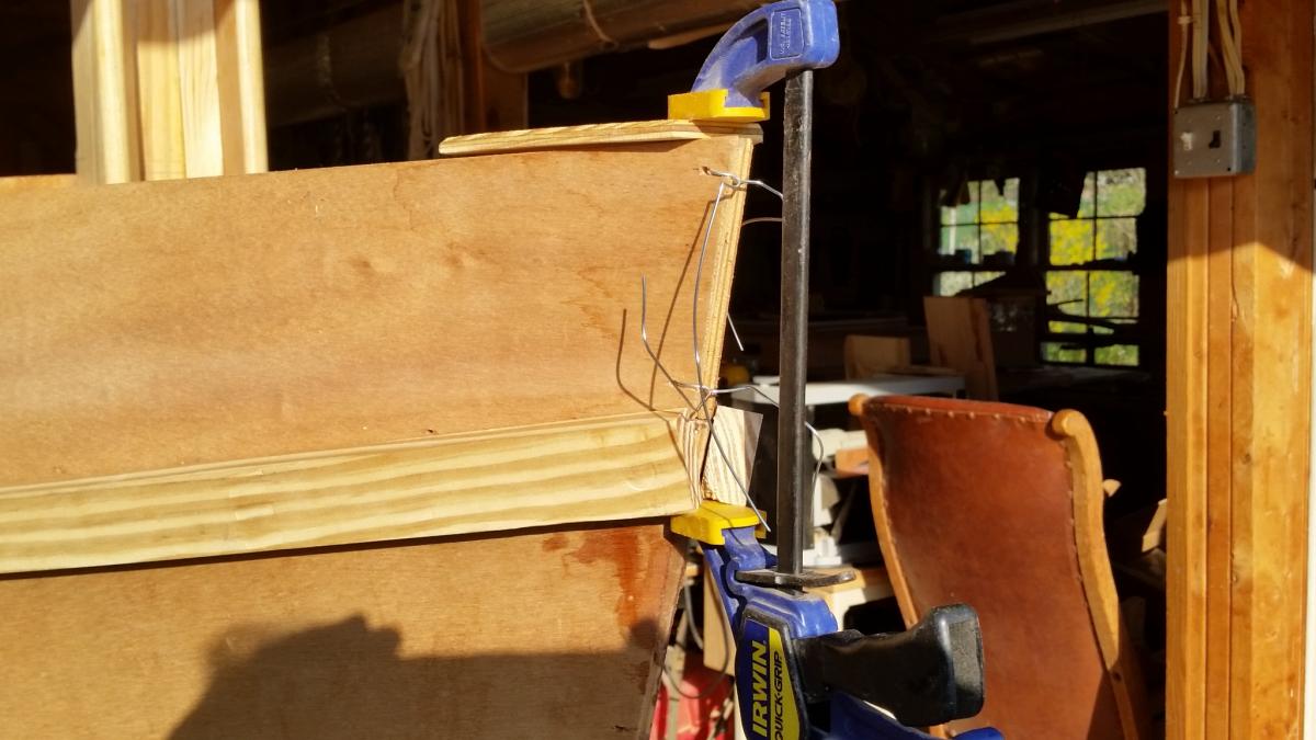
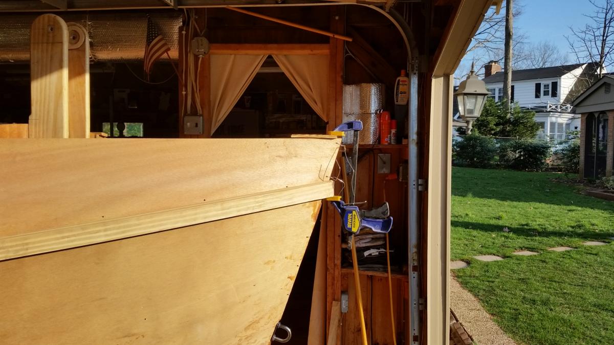
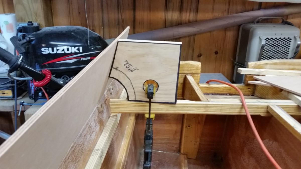
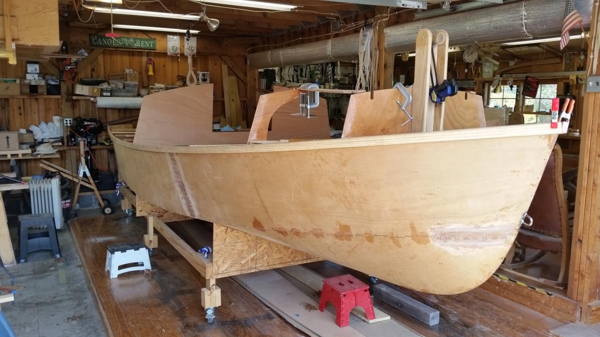
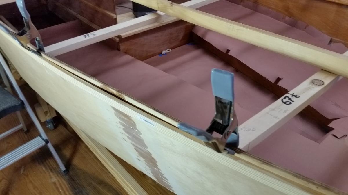
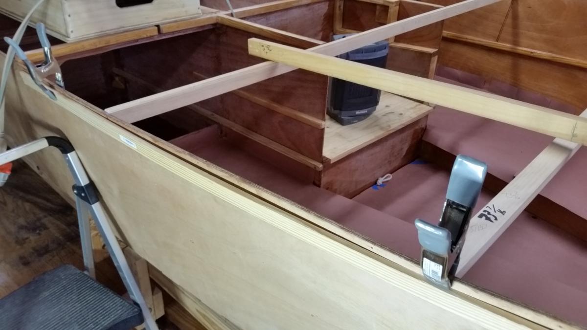
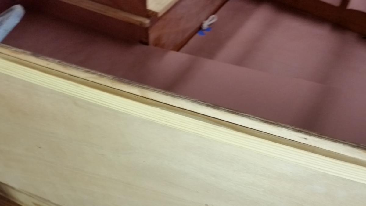
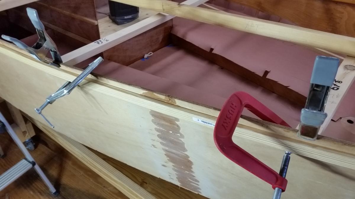
Getting ready to attach the sheer strakes. Both sides are now forced into a fair sheer line from stem to stern. Graham's suggestion of a 1 x 2 batton back-screwed to the side plank leaving a 1/4" lip to channel the strake to its proper position did the trick. NOTICE to builders -- when attaching the transom remember to put a bevel on its sides. Without a proper bevel, the side panels will start forward at a right angle (from the transom) instead of inline with a fair sheer. That will create a slight but noticeable "dimple" in the side panels just forward of the transom. See the photo showing the gap near the transom. I didn't want to force the dimple to be in line with the batton-- thinking that might force the epoxy to crack at the side panel / transom joint. Also, forcing the side panel to the batton wouldn't take the dimple out all the way down to the chine. If the dimple is obvious and ugly, I plan to eliminate it with epoxied fairing compound. QUESTION: Should that be done before or after glassing the bottom and sides? Next will be to firmly line up the sheer strakes to closely fit the side panels and FIX them in place with "spot welds."


-
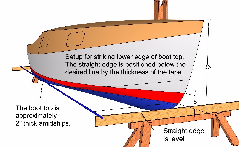
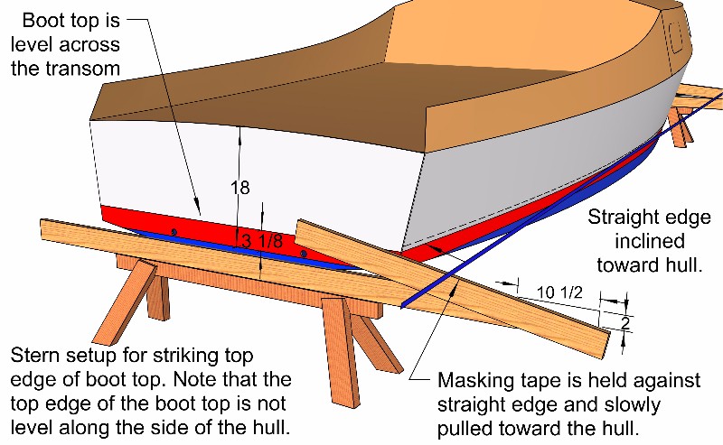
Graham (or Alan) sent me the following four diagrahams. I'm building a Cs20.3 -- so I assume they apply to the 20 footer and not the Cs17. But I'm not sure. Maybe these will help.


-
Summer Breeze - Core Sound 17, Mk-3
Pete McCrary replied to Chick Ludwig's topic in B & B Yachts Forum
Chick, Why do you epoxy spars when you will also have to varnish them with a uv blocker. Not being immersed in water, won't the varnish keep them waterproof from rain, hail, etc? -
Core Sound 20 Mk 3 -- #4 "Chessie" . .
Pete McCrary replied to Pete McCrary's topic in B & B Yachts Forum
Me too, about the sailing together. I don't have a firm target date for finishing "Chessie" (because it takes a lot of the fun out of the project), but I'd love to make the October mess-about. -
Summer Breeze - Core Sound 17, Mk-3
Pete McCrary replied to Chick Ludwig's topic in B & B Yachts Forum
I'll do that. And I'll laminate two pcs for each sprit which will stiffen them. White Pine is very flexable and needs to be stiffened. For my "Tattoo" I made a mizzen mast out of WP and it weighed just under 5 lbs! It had a 1" diameter hollow space thru about 80% of its length. -
Summer Breeze - Core Sound 17, Mk-3
Pete McCrary replied to Chick Ludwig's topic in B & B Yachts Forum
Dave,... I have some high quality White Pine available here. Also Yellow Pine up to 16 foot lengths. The white would be much lighter than the yellow. Which would you consider as best for the purpose? -
Core Sound 20 Mk 3 -- #4 "Chessie" . .
Pete McCrary replied to Pete McCrary's topic in B & B Yachts Forum
Chick,... I just set up the rig to scarf the two 16-footers to two 8-footers. The photos shows the set up. I'll try to do the epoxying this afternoon because we are expecting a bit of snow Saturday night. I'll have to leave my garage door open while the epoxy cures Shown here is my present design concept for the cross-section of the rub rail. It should be pretty easy to fabricate. With the inboard shallow v-cut, it should be fairly easy to have her lay right on the sheer line. I plan to taper each as they approach the stem. Probably not [tapered] at the stern where they would provide some protection to the outboard edges of the transom. I think I should have a SS half-oval the length of the rub rail. Do you know the pros & cons as to the "solid" or "hollow-back" types? Having done this already, do you have any suggestions? Also, do you think it would be wise to attach the rub rail with screws and bedding compound so that it may be more easily replaced if damages -- as opposed to making it permanent with screws and thickened epoxy?


-
Core Sound 20 Mk 3 -- #4 "Chessie" . .
Pete McCrary replied to Pete McCrary's topic in B & B Yachts Forum
Taking Graham's advice I just found a very nice piece of clear 1 x 8 Yellow Pine 16' long with grain straight as an arrow. Combined with an 8' piece of left-over cleat stock I can fabricate a pair of 1 x 2 battens the length of the sheer (just under 21') needing just one scarf each. Later, after trimming them to a desired cross section, I'll use them as rub rails. The photos shows the planks with the scarf cuts made and ready for thickened epoxy. A scarfing jig I made I-don't-know-how-many years ago. My neighbor and boating friend, Henry Felber, helped me steady that 16' board while ripping it and cutting the scarf wedges. I suppose it might be possible to do it alone -- but tricky and possibly dangerous. Next I'll set up and glue the scarfs and let them cure over a few warm days before back screwing them to the outside of the sheer -- assuring fairness from stem to stern.


-
Steve, I wouldn't push the side(s) in to make it fit. It will put a dimple in the side that will be easily seen. Suggest making the bulkhead bigger to fill the gap or adjust its position. Be careful. As with almost everything on a boat -- doing something here often means something (maybe) unexpected happens somewhere else.
-
Core Sound 20 Mk 3 -- #4 "Chessie" . .
Pete McCrary replied to Pete McCrary's topic in B & B Yachts Forum
Graham, Yes, I can see that trying to make that batten double as a rub rail is just "a bridge too far." Better to take on just one thing at a time. Today I'll shop for some good & straight 1 x 2 stock. Can't wait to get those strakes on. Thanks for sharing your practical experience. -
Core Sound 20 Mk 3 -- #4 "Chessie" . .
Pete McCrary replied to Pete McCrary's topic in B & B Yachts Forum
Graham, I can instantly see the utility of the 1 x 2 back-screwed the entire length from stem to stern with a 1/4" proud lip. Perfectly solves the un-fairness problem that I saw between Blks 2&3 and Blk 5 & the transom. I'm assuming that you scarfed (with 8 to 1 slopes) two or more pieces together of clear straight-grain stock from the Home Depot (or local lumber yard). Did you back it with packaging tape to keep it from being glued to the hull and sheer strake? But I'd like to consider gluing it on as a permanent rub rail -- tapered as it nears the stem and the transom. Rather than a 3/4 x 1-1/2 cross section -- that 1x 2 stock could be trimmed as an attractive oval on the outside and a shallow "v" on the inside to match the angle that the sheer strake makes with the side strake. Would ash or white oak (both available here in long lengths & good quality) be too heavy? Would yellow pine be OK? It could be topped with a SS half oval to resist scuffing at the docks. Or is this not a very good idea? -
Core Sound 20 Mk 3 -- #4 "Chessie" . .
Pete McCrary replied to Pete McCrary's topic in B & B Yachts Forum
Steve,... When I picked up my hull Graham gave me advise that each cross member of the module should be individually fitted to the bottom profile before assembly. The precut pieces were machine cut as if no filleting was needed at the keel and chines. Every piece needed to have significant material removed at those points. Maybe you didn't have the benefit of that advice. To fix what you now have -- try this: A. Wedge up the module so that 1) at least one point on the module bottom (the "proudest") touches the hull's bottom, and then 2) adjust the module so that the top of the footwell sides are exactly above the lower edge of the rabbit in the transom cut for the cockpit deck a distance of D" and the corners of Blk#4 at the sheer are the same D" above the edge of both port & starboard strakes. If the transom isn't epoxied in place, it should be wired just where it should be so that its rabbit is in the correct position as a reference line. Holding everything steady, carefully find and measure the largest gap between the module and the hulls bottom -- that's your G" dimension. Your trim dimension T" is the minimum of D" and G". B. Cut a small piece of wood T" thick. C. Then, holding the module steady, mark every piece that should bare on the hull, using the thickness of the piece (cut for that purpose) as a guide for your marker. The only pieces not marked should be those that were at the G" maximum gap OR those where their gap is > T. D. Remove the module, turn it over, and trim off all the "high" pieces to the lines you marked. E. When the module is replaced it should be a pretty good fit if T is > G. If T < G, then some pieces will show a gap. But those should be less than before the trimming and you should be able to close the gaps with thickened epoxy. I know it's a lot of trouble. Don't worry that a lot of material is removed near where the fillets are. It's at the edges of the fillets that should be close. And it's OK to expect the centers of the panels to show a little gap because of its natural bulging. Maybe this will work for you. -
Core Sound 20 Mk 3 -- #4 "Chessie" . .
Pete McCrary replied to Pete McCrary's topic in B & B Yachts Forum
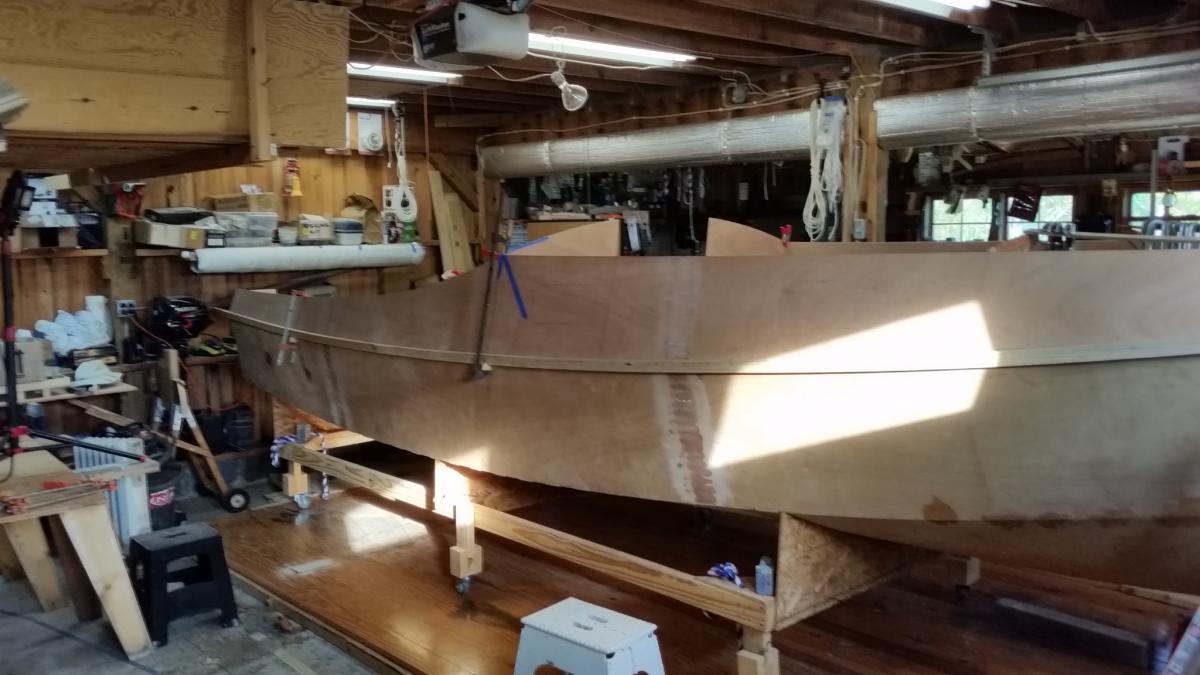
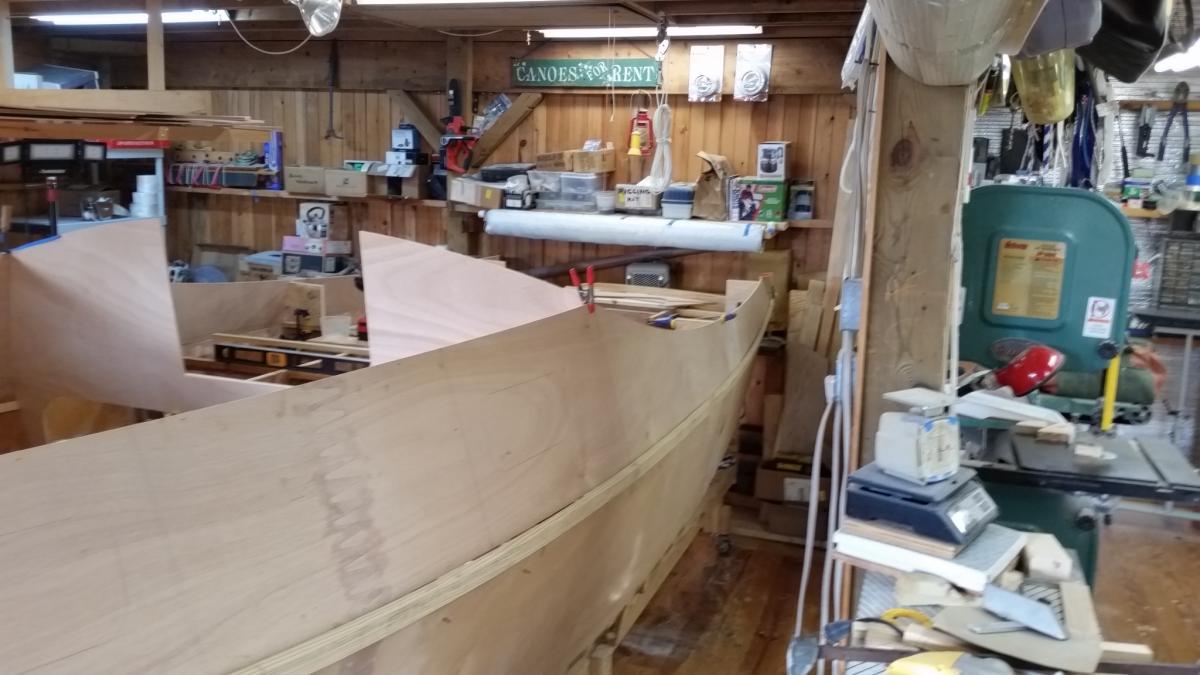
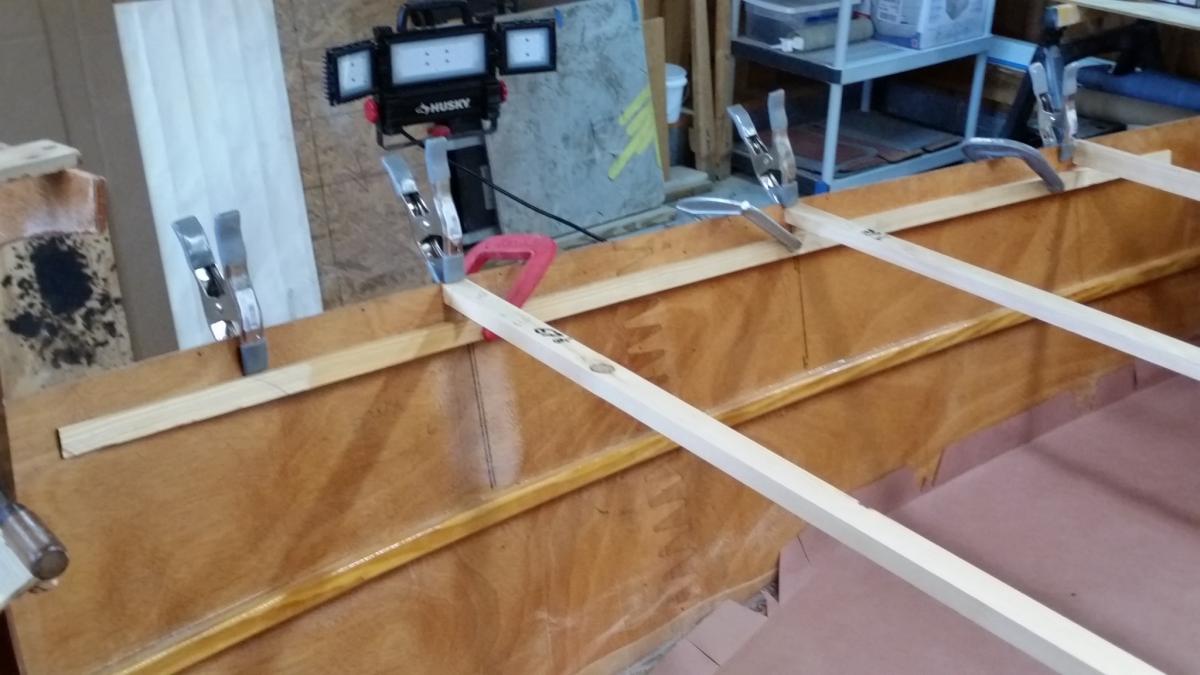
Now I'm getting ready to wire on the sheer strakes. Alan alerted me to a problem noticed with some other builders. It appears that after unfolding the hull and installing Blks 1 & 2 and the module, the shape of the hull (at the sheer line) between Blks 2 and 3 is slightly narrower than the design dimension. I think that should be expected considering the distance between Blk 2 and Blk 3. Unless corrected, this leads to the hanging knees leaning inboard a bit so that the roof line and companionway hatch won't line up with the design positions and for the carln knotches in Blks 1 & 2. Alan recommended "some temporary props put in place across the inside of the hull until the sheer strakes are installed." He gave the inside beam design dimensions (at the sheer line) as 67-1/8 at the first hanging knee and 73-7/16 at the second knee. So I cut the beam props to the specified lengths and inserted them at the knee positions. For the aft knee I needed to stretch the sides out about 2.5" and the forward knee almost 2". But the side strakes (at the sheer) were no longer fair. There were kinks where the props pushed out the sides. The next two photos show a fair batten clamped to the outside. Notice the kinks and "air-gaps." Thinking that a thick stringer on the inside would force the sheer line to be closer to "fair" -- I cut two stringers (3/4 x 1 x 80) -- the last 10" at each end tapered down to 1/4". I copied the designers stringer cross section of 3/4" x 1". The following photos shows the "air-gaps" almost gone. I plan to move the temporary props to push on the stringer in at least two places -- cutting the lengths to what will make the ID at the sheer match the design dimensions. By doing that (and not pushing out on the strakes' edges -- I think the strakes will be perfectly fair. Hopefully! I'll place the stringers just about 2-1/2" below the sheer edge so that I'll have room to wire on the sheer strake, fillet, and glass tape the intersection, stem to stern. The stringer will first be clamped in place and then "fixed" with two drywall screws spaced about 10" apart at the center (all clamps removed). I think I'll put packaging tape on its underside so that any spilled epoxy won't bind it permanently to the side strake. I'll remove the stringers after the filleting and glassing cure for a couple of days. Any predictions on what the "spring-back" will be after the stringers and props are removed? My guess is maybe about 1/4" each side MAX. Should I anticipate the "spring-back" and push the setup dimensions an extra 1/2"? Does anyone have any actual experience with this problem. Am I missing anything? Comments and suggestions would be appreciated.


-
Core Sound 20 Mk 3 -- #4 "Chessie" . .
Pete McCrary replied to Pete McCrary's topic in B & B Yachts Forum
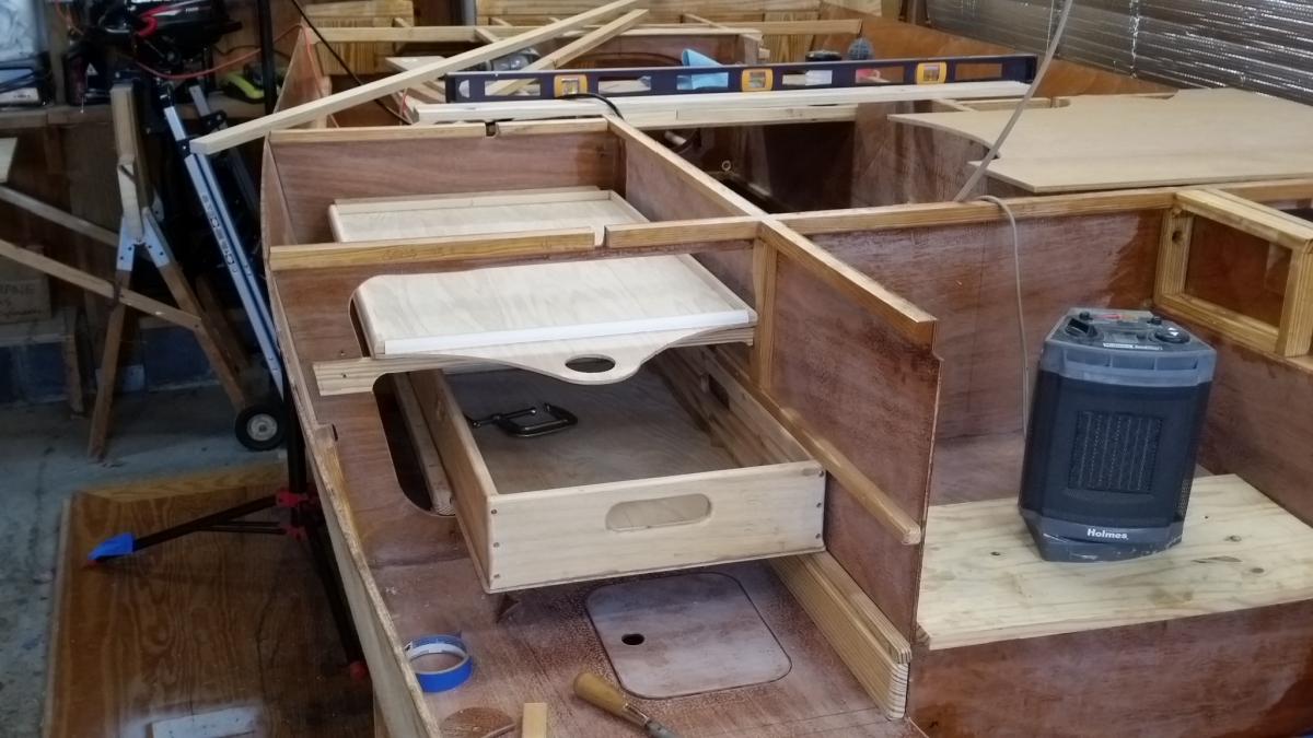
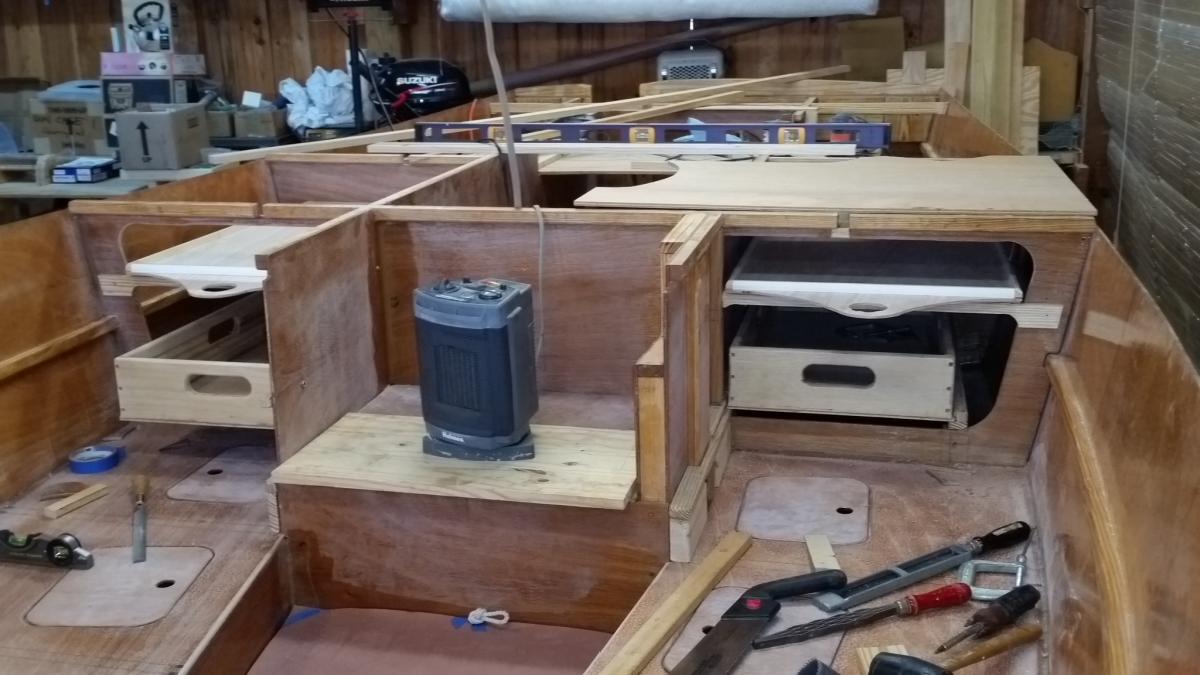
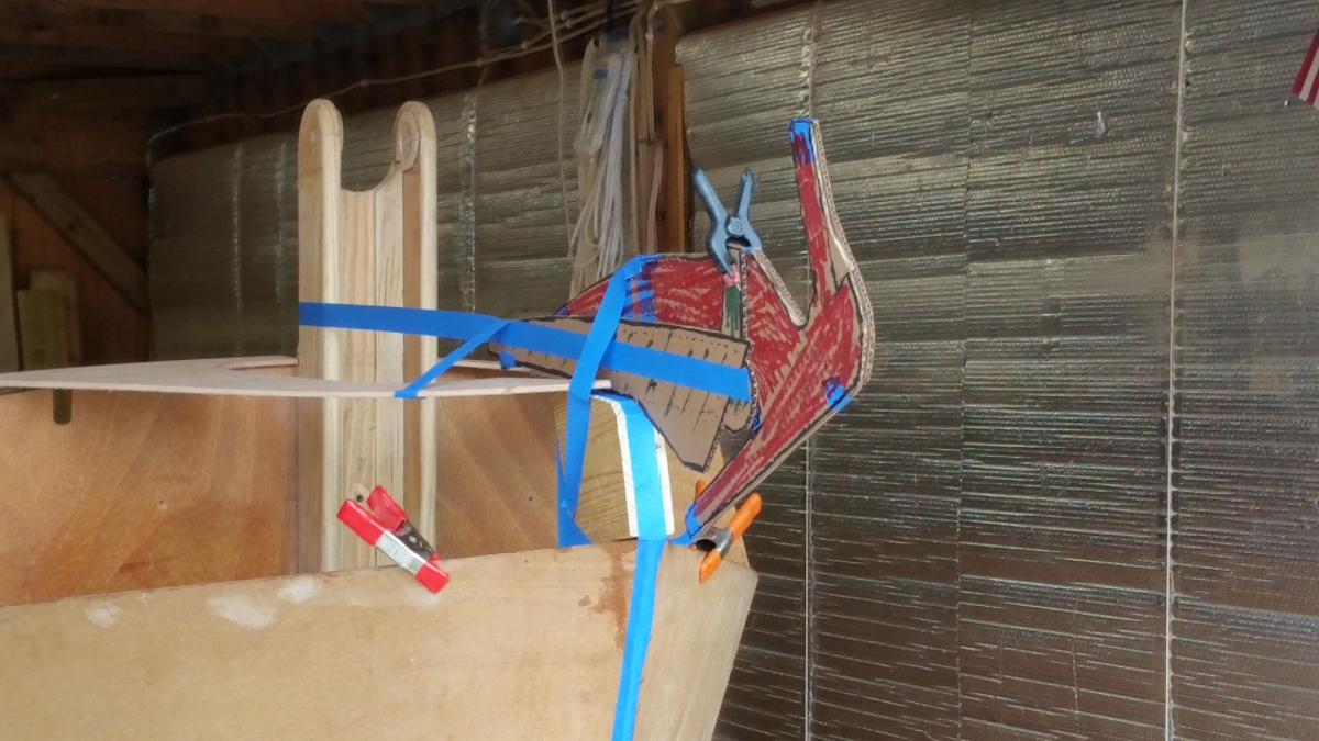
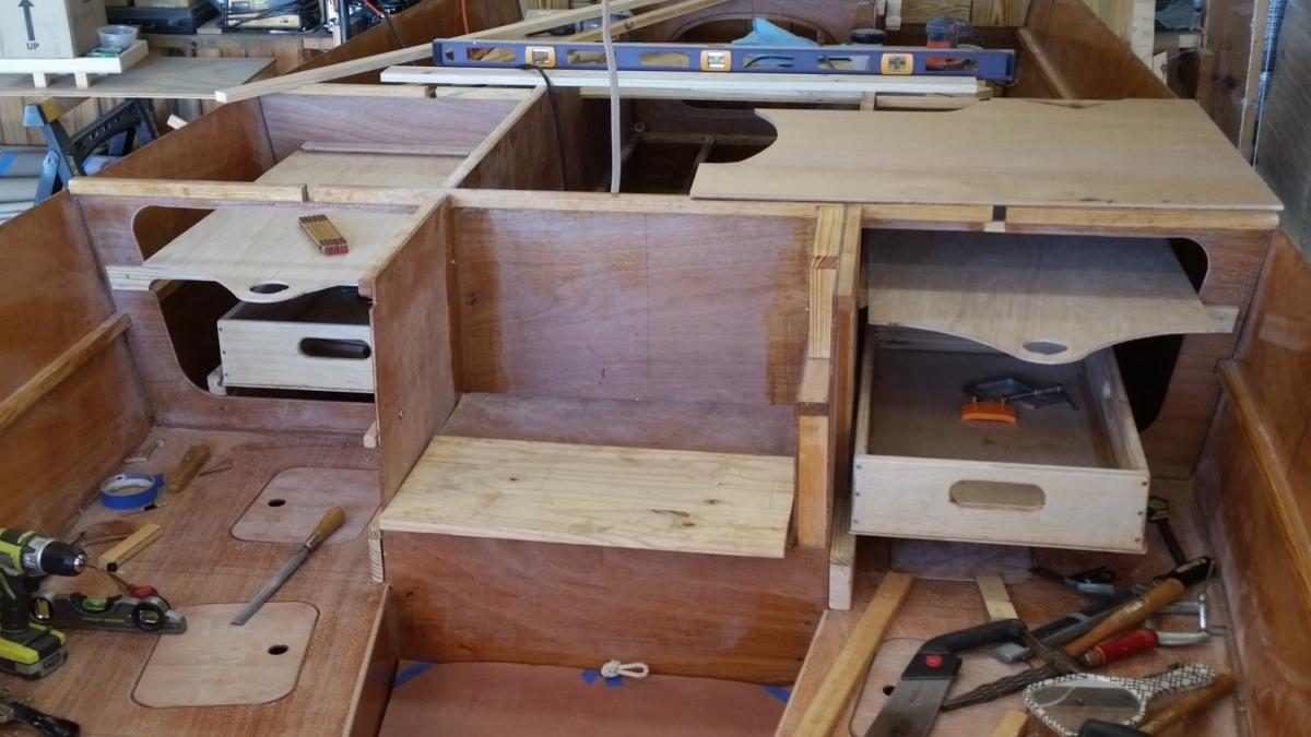
Well, guys ... I'm getting closer to wiring on the sheer strakes. Here's what I finished yesterday. The quarter-round edges to the slide-out shelves were screwed on (to be glued later). Under the adjustable shelf I attached a 3/4" beam on its centerline (tapered to 1/4" at each end) to stiffen it length-wise. Before gluing, all exposed edges and corners of the shelving and support pieces will be rounded over. I'm thinking that I won't epoxy any of this, but will prime and paint. The last photo gives you an idea of what the port-side drawer and shelving will look like from the cabin after the Blk #3 is in place along with the cockpit decking. I'd say NOT EASY to get to. But these drawers and sliding shelving will make access much easier. Under the drawers there is lots of space for several gallons of drinking-water bladders. Down as low as possible -- providing extra weight at least down low. This morning I fretted with how I would deploy my anchor, handle its chain and rode. I've gone to the Internet for anchor rollers. Actually order one, which had to be returned as totally not appropriate for a Cs20.3. Finally found a "Marine Stainless Steel Hinged Self-launching Bow Anchor Roller 16-1/2" for Boat" by Five Oceans. The Amazon web page had a dimensional drawing. Using that and my 13 lb Rocna anchor -- I cut full-scale templates so that I could visualize an installation. It looks like it will be a very good fit just on top of the foredeck at the stem. I've already cut and fitted a breasthook at the top edge of the side strakes. That will be built up between the sheer strakes (and under the foredeck) to make a solid foundation for attachment. The angle of the Anchor Roller will be set slightly (pointing to port) so that the pull of the rode on the starboard side of the tabernacle will be "in-line." The first 10' (or so) of the road is chain. I'll need some kind of chain grabber so that it can be secured when the anchor is fully retrieved into the roller. Probably find a place for it on the starboard side of the foredeck. When deployed, I think that I'll belay the three-strand rode to a cleat on the starboard side of the tabernacle. It will, of course, have to have a secure base. My goal is to be able to accomplish (single-handed) any and all anchor tasks while standing on the forward bunk up-thru the the forward deck hatch WITHOUT EVER NEEDING TO CLIMB UP ON THE CABIN ROOF! I would really welcome any critical commentary on this approach. Also, ideas on the placement of such deck hardware that's needed to handle the anchor's rode, both chain and three-strand.


-
Aren't the bunks parallel to the waterline? On a dead level wood shop floor and the hull on its design cradle -- my bunks and the forward locker top are also dead level. And the cockpit seats port-to-starboard are also level. However, the cockpit seats show about 1/4 bubble aftward slop. And the footwell sole slightly more slope.
-
Core Sound 20 Mk 3 -- #4 "Chessie" . .
Pete McCrary replied to Pete McCrary's topic in B & B Yachts Forum
I keep finding things to do before wiring on the sheer strakes. My latest are sliding shelving up under the cabin space between Blks 4 & 5. The shelf height has 3 adjustable locations -- below the underside of the cockpit deck by 4.875", 3.875", and 4.75". The supporting shelf is actual 1/4" regular plywood. It has (underneath) a 3/4" square beam on its centerline for support. The sliding part is 3/16" ply with an oak veneer (top & bottom). It will have 1/2" x 3/4" quarter round on all 4 sides (flat side facing inward) to stiffen it. I'm thinking the spaces could be used for stowage of drop-boards, drop-screens, hatch screens, charts, notebooks, socks & underware, pjs, pretty much anything fairly light, etc. It would remain dry even if the crew left the companionway hatch open during a downpour (while out-to-lunch, literally and/or figuratively). After I add the quarter round I'll attach more photos. Maybe this will complete my pre-closeup tasks -- unless you guys can suggest more cool things easier-to-do-now than later.

-
I say now is the best time to mark the waterline on the bare plywood. Make it permanent into the wood. Press hard with a carpenter's pencil. It will show thru the epoxy and fiberglass. If your floor is level and the cradle & boat also level it's fairly easy. Just make a vertical stand the top of which is at the waterline height and move it around the boat, marking the hull, then "connect the dots" (or little dashes). Strike the line hard onto the wood. Put a little paste or bee's wax under the stand. For the top of a parallel boot add a block (off of a 2 x 4) for a 3.5" boot -- and strike another line. But Graham's boots have an attractive taper to them. If you want that, it's a bit more tricky and Graham's method is a beauty. But by either method, I'd do it on the bare wood.
-
Summer Breeze - Core Sound 17, Mk-3
Pete McCrary replied to Chick Ludwig's topic in B & B Yachts Forum
Thanks Paul. I'll pay attention to it before painting or varnishing. But a QUESTION: Does sanding take the blush off with the sanding dust? -
Summer Breeze - Core Sound 17, Mk-3
Pete McCrary replied to Chick Ludwig's topic in B & B Yachts Forum
The bristles on Grandpa's brush are 3" long. The cross section is oval including the handle. It's a nice easy grip that naturally resists rotational torque. I don't think it's hand carved nor turned on a regular lathe. Maybe on the thing that turns out assymetrical ax handles. I counted 5 x 14 sets of bristles. The wood handle isn't a hard wood like oak, ash, or maple. But it's that color and close grained. And I don't think it's pine or poplar. Maybe spruce? When I acquired the brush some 40 years ago, it had a 1/8" hole thru the end of its handle. I think it had a string thru the hole. Don't know if Grandpa drilled the hole -- could be it was always there. -
Summer Breeze - Core Sound 17, Mk-3
Pete McCrary replied to Chick Ludwig's topic in B & B Yachts Forum
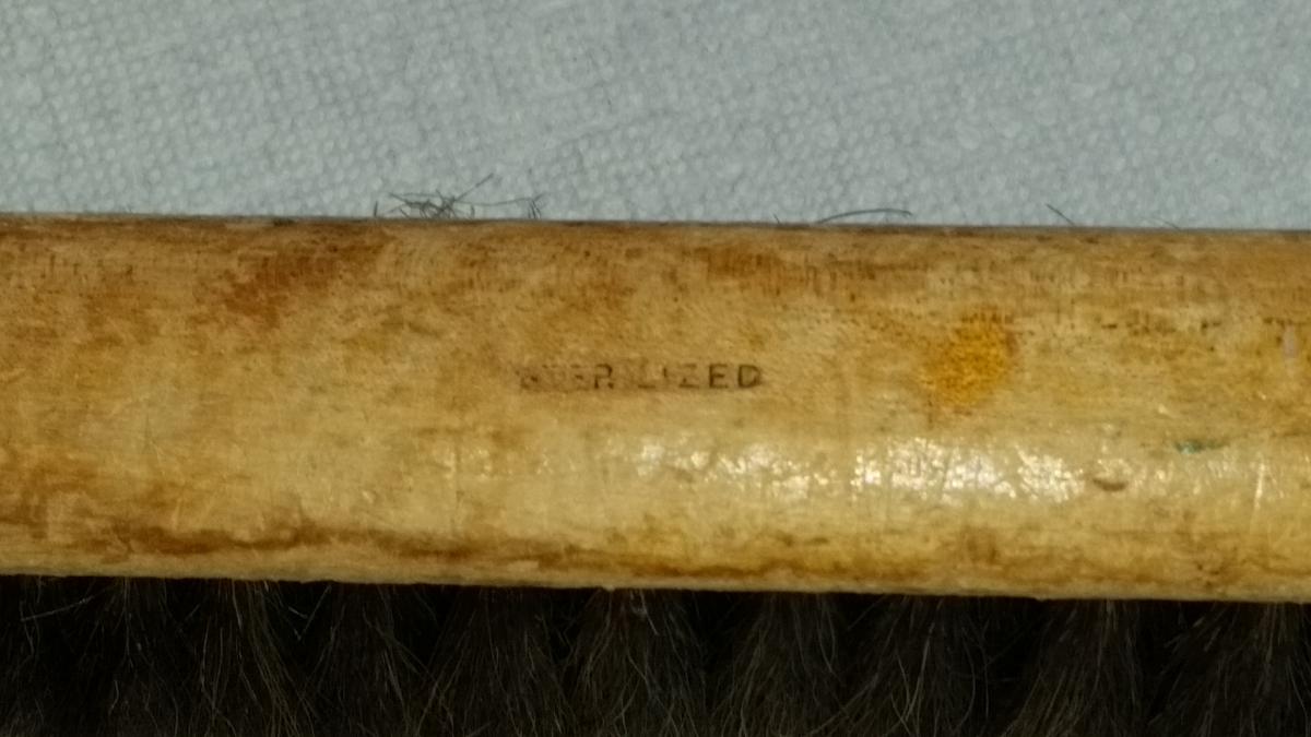
Par & Chick,... Here are two photos of my brush: The only identifying mark is the word "STERLIZED" impressed on the top. I don't understand the need for such a label. I suppose this brush could be used for another lifetime.

-
Summer Breeze - Core Sound 17, Mk-3
Pete McCrary replied to Chick Ludwig's topic in B & B Yachts Forum
Chick, I'm using B & B epoxy and fixer -- and haven't noticed any "blush." What's it look like. Building 3 boats with West System and 2 with MAS -- I didn't pay much (really, any) attention to it. Paint and varnish went on ok. Have I been screwing up and not even knowing it? When I built my cedar-strip canoe I went to great pains to vacuum and wipe all surfaces in the shop trying to remove all dust. Even spread oil soaked something or other (from True Value hardware) on the floor and swept it up. I got a nice bright varnish on the cedar strips, but it still wasn't perfect. For the next 4 boats I didn't bother to the same extent -- just dusted with a bench brush and swept the floor. I did use a tac cloth on the surfaces to be painted or varnished. Maybe the finishes weren't perfect, but (as the antique car restorers say) they all look good at 20 feet. By the way, I have my grandfather's bench brush which he must have used in his shop around year 1900! I don't know what the bristles are, but its quality can't now be duplicated. I'm told that he was in the Clemson class of 1889 in one of their first class of EE majors. His hobby was woodworking and we still have (and use daily) some of his hand made furniture. His name was John Adger McCrary and was born in Anderson, South Carolina, and worked for the Navy's Bureau of Ships in Washington -- retiring after the war in the 1940s.