Pete McCrary
-
Posts
692 -
Joined
-
Last visited
-
Days Won
40
Content Type
Profiles
Forums
Events
Everything posted by Pete McCrary
-

Core Sound 20 Mk 3 -- #4 "Chessie" . .
Pete McCrary replied to Pete McCrary's topic in B & B Yachts Forum
Getting closer to the "rollover" event. The roof-support structure is all-but complete. Next will be glueing in-place the companionway & hatch frame, which is presently curing on the bench. The outboard beams are also glued in-place. After all the roof-support structure is glued in-place, I will "fine-tune" the bevels and beams to achieve an "fair" match to the roof panels. Those panels are my next step: I'll epoxy (two coats w/o FG) and then "butt" them together the entire length of the centerline (leaving spaces for the xbeams). The butt-plates will be on the underside. On the topside I'll epoxy on a 3" FG tape along the centerline. Outboard beams attached to Blks 1, 2, & 3 and fwd & aft knees. The companionway & hatch framing curing on the bench. Also, the battery base. Once the roof panels are joined, they will be the largest one-piece of plywood that I have ever attempted to do anything with. I'm thinking that I'll move it in-place for a dry-fit with 1" dry-wall screws -- carefully "indexing" its position in multiple places. Then mark the underside with the profile of the support beams and inwales. When the panels are removed [from the dry-fit}, the gluing surfaces will be sanded. Finally, the gluing surfaces will we wetted with neat epoxy and then thickened epoxy applies to the support beams and inwales. Then the hard part -- getting that huge roof panel in place and secured without scraping off all the glue. I'd APPRECIATE any helpful tips or suggestion on how to get this done.

-
Core Sound 20 Mk 3 -- #4 "Chessie" . .
Pete McCrary replied to Pete McCrary's topic in B & B Yachts Forum
BATTERY Mount . . Earlier I installed a battery box just above the keel inside the forward locker (between Blks 1 & 2). But now I've decided to follow Gramh's suggestion that a good place for the battery is on the keel just forward of Blk 3 under the first step from the cabin sole to the bridge deck. The Group 24 battery box is removed and on a shelf in my shop. I suppose it could still be used for a 2nd battery (but not likely). The battery is a Group 27 "deep cycle" and rated at 92 amp-hrs. It's equivalent to about 58 lbs of ballast on the keel at mid-ship. The installation required modification of the removable cabin sole. It will fit nicely under the first step of the removable 2-step "ladder" leading up to the bridge deck. That ladder has not yet been designed. I'd like it to serve another purpose -- table, stool, game board ??? Suggestions please. The battery base not yet epoxied to the keel. Modified cabin sole in place. Battery clamped down. Showing battery top just below shelf for the Port-a-Poti. Just yesterday I completed all filleting and FG taping all interior corners and the sheer strakes to the side panels. Today I'll be measuring, cutting, and trimming the remainder to the cabin [roof] beams. After that I think I'll be ready to install the cabin roof.


-
Core Sound 20 Mk 3 -- #4 "Chessie" . .
Pete McCrary replied to Pete McCrary's topic in B & B Yachts Forum
AMAZING ACCURACY -- From the keel to the top of the roof, the port and starboard cabin knees meet the companionway frame just 1/8" from the same elevation. And their spacing, port to starboard, was < 1/4" error from meeting right at the side of the frame. The cabin "hanging" knees rest on the longitudinal stringers glued to each side panel between two parallel "computer-drawn" lines. If either line (or the placement of either stringer) is off just a little -- then that error will be evident (even multiplied) by the time the builder is installing the companionway frame. I'm getting close to roofing the cabin. I think that I'll roll "Chessie" over when the roof is secured in place -- leaving hatch fabrication and cockpit decking for later. However, I will have the cockpit sole and deck "dry fitted" and secured temporilarily with drywall screws to add some stiffness for the roll. In addition to completely finishing all that's required on the bottom, I will paint the cabin interior "overhead" areas while they are "up-side-down." Hopefully, when rolled upright, "Chessie" will never again show her "bottom up" !! Frw knee about 1/8" shy of companionway frame. Aft knee only about 1/16" shy. Shimes cut and glued to make the knee tops fair. The knees of Blk 2 were about 3/16" proud of the frame and will be trimmed with a spokes shave. COMMEMTS & SUGGESTIONS welcome regarding my plans for the rollerover.

-
Core Sound 20 Mk 3 -- #4 "Chessie" . .
Pete McCrary replied to Pete McCrary's topic in B & B Yachts Forum
Now I'm ready to fillet and glass the corners all around the inside from stem to stern. This is how I got there: 1. Graham's posting that he "back-screwed" a .75" x 1.5" fairing batten (stem to stern) on "Carlita" made (in my opinion) all the difference in preparing for installation of the sheer strakes. And those battens can be effectively used [later] for rub rails. 2. With the cabin knees wired in place and with the design beam dimensions at the cabin knees (that Alan provided), I was able to come pretty close to those dimensions by jamming spacers at the sheer line. 3. With the beams braced close to the design at the sheer line and at the tops of the sheer strakes AND (aft of the cabin) the strakes braced at the 75.2 degrees (provided by Graham) -- I then tightly wired the knees and Blks 3, 4, & 5 to the side panels and sheer strakes. 4. Then notches were cut where needed and the cabin /roof inwales were dry-fitted making quite fair the top of the sheer strake all the way from the stem to Blk 3. 5. Then I did the tac welding everywhere (except for the inwales). After releasing the bracing, there was very little "spring-back." 6. The next two days I removed the inwales (for minor adjustment and trimming) and upon replacement, glued them in place forward of Blk 3 and then [next day] the inwales aft of Blk3. At this point the whole structure is very stiff. 7. Previously I had built the frame for the companionway-hatch module (OD of 24.5") to fit between Blks 1 & 3. It was made an exact rectangle with cross beams aligned exactly with the forward edges of Blk 2, fwd knee, and aft knee. The beams were oversized in height so that the arc of the cabin roof could later be marked and cut on each beam. 8. The notches in Blk 1 were each cut 1/8" wider so that Blk 1 and Blk 3 would form a perfect rectangle with an outside dimension of 24.5". 9. Using a very straight 1 x 2 batten laid fore and aft with ends fixed at their appropriate notches, I marked the ends of the knees (Blk 2, fwd & aft knees) to be "in line." Two were already "just right", and four needed slight (< 1/4") trimming. After trimming (with saber saw), all lined up very nicely. 10. Finally, the previously constructed frame dropped nicely into place. Notice the oversized beams. The beam (cleat) on aft side of Blk 1 has already been trimmed. This is Blk 2 showing it's about 3/16" high. That carries off to the side as well (on both sides). It's definitely higher than the other knees. It seems to be properly placed with its angle right at the sheer -- so maybe the upper dimension [as cut] may be off a bit. This is the fwd knee. It's a little shy of where it should be. Probably because I couldn't make (force) the beams just wide enough. Probably that's also why some of the knee ends needed to be trimmed. My plan is to cut thin shims and glue them to the top of the [shy] knees -- then trim them to be fair with the other knees and Blks 1 and 3. For those that are high -- I'll trim them with a saber saw or maybe spoke shave. Notice my "Construction Spacer." After I mark the beams with the profile of the cabin roof, I'll place the Construction Spacer next to the beam to be trimmed before its removal. Looking forward. The lower edge of the beam (cleat) at Blk 1 is cut at 1.25". This brings its lower (roundovered) edge just at the upper edge of the 1/4" roundover on the lower edges of the 1.5" longitudinal beams. It's my plan to make all the beams that width. My measurements show that both top edges of Blk 2 are 9/64" high, stbd fwd knee is 1/32" low, and stbd aft knee is "right on"; and on the port side the fwd knee is 5/32" low, and the aft knee is 1/8" low. I'm very pleased and impressed with the accuracy of this kit -- especially this far into the construction. I noticed that the side gaps are a little more on one side than the other. When installing the module it slipped into place with such a solid "thunk" that I didn't think to carefully inspect if it was perfectly centered. It probably could have been jiggled just a little -- then that small error could'v been multiplied later on in the construction. All-in-all, I think this kits accuracy is absolutely amazing. Pete McCrary, a happy builder.


-
Core Sound 20 Mk 3 -- #4 "Chessie" . .
Pete McCrary replied to Pete McCrary's topic in B & B Yachts Forum
One more thing done. The "inwales" aft of the cabin are now set in epoxy. This setup was much more difficult than the ones for the cabin roof. Probably the compound curve that required the batten to be split [for about 36") in order to make the "ski-jump" curve up to the cabin roof. Wow !! Looking more like the boat I want to build. This is fun. Does one ever have enough clamps? Keeping the sheer-line profile "fair" at the cabin / cockpit transition. A port-side outboard view. Tomorrow I'll start making the companionway frame and roof beams match the design cone or (perhaps) a cylindrical shaped roof.


-
If you want (or an EMERGENCY REQUIRES you) to sail at night, you need three lights: red, green, and white (port, stbd, and aft-facing). It's just a question of how to power them and where to place them. I'd say "top of the mast" is most convenient -- provided you have a central power source (say a 70 to 90 amp-hour 12 volt battery). The central power and a wire up the mast eliminates the need for clamp-on lights and their stowage / deployment and also dealing with dry-cell batteries. If you want to use your outboard engine at night (either by itself OR while also sailing) you must (IN ADDITION to the red-green and aft-facing white light) have a white light facing forward approximately 6' above the deck. That light is often called the "masthead" light (a misnomer). If you also anchor at night you need a third white light that can be seen from a complete 360 degrees. That one is often on the top of the mast and is sometimes called a "masthead" light (not a misnomer). However, if you have a 3-way light at the masthead, then it [the anchor light] needs a separate circuit and more wires up the mast and a more complicated connector. The anchor light can be any all-directional lamp hoisted to any convenient elevation. It needs to be bright enough to be seen from 2 miles.
-
Core Sound 20 Mk 3 -- #4 "Chessie" . .
Pete McCrary replied to Pete McCrary's topic in B & B Yachts Forum
Little-by-Little -- and progress is made. Graham recommend that a 5/8" x 1" batten be inserted inside the top edge of the sheer strake at its intersection with the cabin roof. Notches had to be cut in Blks 1, 2, & 3 and the cabin knees. Now the sheer strake is beautifully fair from stem to Blk 3. The battens are a little proud of the roof beams so that they may be bevelled for a neat fit under the roof panels. Tomorrow I'll install another pair of battens from Blk 3 to the stern. I think a boatbuilder's term for this part is a "clamp." Like a "sheer clamp" providing a means of attaching the deck to the hull along its sheer. I could be wrong. Here, would it be a "cabin roof clamp" ??
-
Core Sound 20 Mk 3 -- #4 "Chessie" . .
Pete McCrary replied to Pete McCrary's topic in B & B Yachts Forum
Fabricating rub rails for "Chessie." With the sheer strakes tac welded in place, I removed the 20 foot (plus) 1 x 2 (.75" x 1.5") yellow pine fairing battens that were back-screwed to the outside of the side panel with the top edge about 1/8" proud of the sheer. That really smoothed out the entire sheer line. Now I have two long battens that I plan to use as rub rails. However, after being attached to the hull for a over a week, these very flexable battens have a "set" that makes them hard to manage on a table saw. Trying to save space on the shop floor, I clamped them together (concave sides facing each other). That made a very straight and solid piece with a square 1.5" x 1.5" xsection. Fairly stiff and (with a helper) easy to push thru a table-saw setup. Rub Rail xsection based on Graham's design for "Carlita." The drawing shows a pair of rub rails. On the right is one of the fairing battens yet to be shaped -- and on the left is the other batten with the desired shape. These battens will be clamped together for three of the four cuts require (for each side). The cuts c1, c2, and c3 (all with blade angle at 30 degrees) are made in mirror-image pairs -- port and starboard. After the first cut (of each pair) the clamped-together piece is turned end-to-end for the second (the mirror-image) cut. The c4 cuts are made (saw blade straight up) after the clamps are removed and the battens separated. The rub rails will be attached to the hull with their tops just at the sheer/side-panel seam with 1.25" SS FHWS thru the hull and into a .5" x 1.25" inwale. I probably have enough left-over mahogany for the inwales. The three sharp corners will be rounded over with block plane after attachment. My plan is to have the rub rails attached with bedding compound so that they may be removed for repair or replacement. I haven't started their shaping yet -- so COMMENTS & SUGGESTIONS are welcome.
-
Core Sound 20 Mk 3 -- #4 "Chessie" . .
Pete McCrary replied to Pete McCrary's topic in B & B Yachts Forum
I've never even tried to reuse an epoxy roller. I use cheap 9" rollers (cut in half to 4.5"). They are gray in color and have a foam nap of about 1/8" thickness. I have found them in paint stores and True Value hardware stores. -
Core Sound 20 Mk 3 -- #4 "Chessie" . .
Pete McCrary replied to Pete McCrary's topic in B & B Yachts Forum
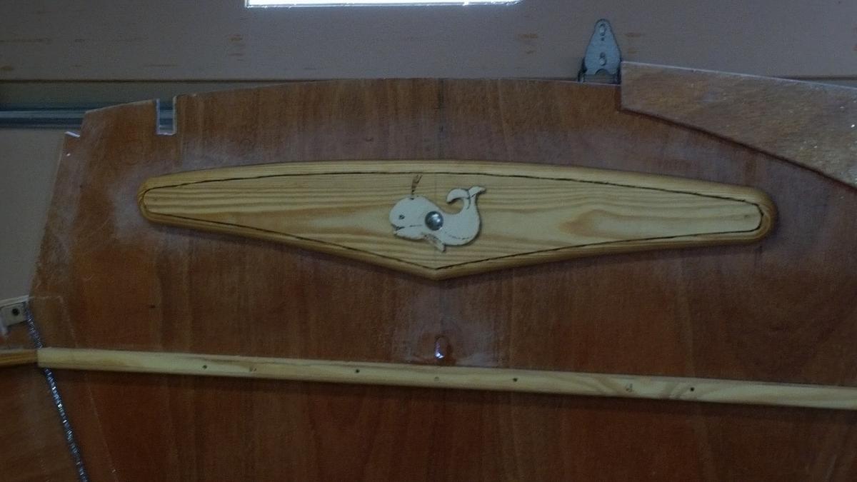
Getting close to attaching the sheer strakes and being able to actually see in real 3-d what the cabin space will look and feel like. To cheer things up I fancied up the doubler I installed to stiffen Blk #1. Probably isn't necessary, but it gives me a little more feeling that the tabernacle can't be made to move. "Chessie" has a small wale as her mascot -- "Chester" -- to keep her safe from the demons of the deep. Although I made space for a battery box in the locker between Blks 1 & 2, I'm going to have the battery in the space right on the keel just forward of the shelf under the bridge deck. Its top cover will be the first (of one or two) steps up to the the cockpit. Its weight (probably about 85 lbs) will be useful as ballast and centrally located. If I ever feel the need for a second battery, I'll use the battery base already made between Blks 1 & 2.

-
It may not matter much -- but another downside to clamping the 2,5 hp Suziki to the transom is that the prop thrust will be about 10 or 11 degree off from horizontal. Up, going forward pushing stern down (bow up) and in reverse, pushing stern up (bow down). That's because the CS20.3's transom has a negative tilt and the Suziki has a built-in tilt (adding to the trnasom's) at its lowest adjustment. Wouldn't matter much around the harbor. But if you needed to make a transit before dark, it could make a difference.
-
I'd say pumps are OK, with certain precautions. You do need to keep the fluids fairly warm, say at least > 70 dF. In my unheated shop I made a HOT (i.e., warm) HOUSE out of 1" styrofoam insulation heated with a 40w lamp. I've never had splattering. Occasionally, the fixer punp needs to be primed if it hasn't been used in a while. Cleanup just needs to have the spouts wiped with a shop paper towel on the outside and a pipe cleaner on the inside. You can see there's room to keep extra epoxy and fixer warm so that they don't chrystalize. Occasionally, the pump shafts need to have the percentage scale remarked as the old marks fade. I first tried a 25w bulb, but it didn't add enough heat (Nothern Virginia). The 40w adds about 20 dF to shop temp. I have two remote temp sensors inside the HHouse -- one transmits to the receiver on its top and the other to a receiver in my kitchen. Although my shop is not heated, I have two 1500w electric space heaters that together can add about 10 dF (to the outside temp) for the whole (3-bay) shop/garage combination. I can drop an insulated roll up curtain to separate the 2-bay garage from the shop. In that arrangement I can add as much as 25 to 35 dF (to the outside temp) for the shop alone..


-
Bob,... Yes, one squirt (sqt) is one each of epoxy and fixer. The pumps were supplied by B & B with their kit materials. I don't know their capacities. Could be "... the typical 1 oz pumps."
-
I thought it would be useful to share some data that I've recorded over several "builds" regarding how much epoxy is needed for several tasks -- such as simply sealing out moisture, application of FG, etc. Most recently (for my "Chessie," a CS20.3) I covered one side of each sheer strake and 4 cabin knees using a 4.5" roller with about a 1/8" foam nap. The first coat required 8 squirts (sqts) each of epoxy and fixer. For the 2nd coat I mixed 6 sqts, and estimated that I had about 1 sqts left over, for a net requirement of 5 sqts. The total area measured (approximately) 38 sqft. 4/24/16, 8 sqts / 38 sqft = 0.21 sqts/sqft for 1st coat on bare marine plywood (Okoume) Same date, 5 sqts / 38 sqft = 0.13 sqts/sqft for 2nd coat ... This is fairly consistent with 0.20 and 0.12, respectively, measured on 11/27/15 on a smaller sample. For application of the 1st coat when covering plywood with 10 oz FG -- requires about 1.1 to 1.2 sqts/sqft. 2nd coat (filling the weave) -- about 0.2 to 0.3 sqts/sqft. For filleting (r= ~ 3/8") -- about 1.5 sqts/linear ft. More for > radii. For glueing -- about 1.0 sqts/sqft Such numbers are, of course, approximate and vary according to materials, the brush or nap of the roller, and other factors. To save epoxy for small jobs, I've found it useful to mark the pump shafts at 20%, 40%, 60%, and 80% of their full strokes. It seems to work pretty well -- at least no problems so far when mixing small batches. I also [sometimes] mark the epoxy level (on bottle) before & after a multi-squirt job. I keep a "build" note book and try to remember to record such epoxy data so that I'll eventually get a fair idea of what's needed for any particular job. But memories fade, and the note book has proved useful.

-
Core Sound 20 Mk 3 -- #4 "Chessie" . .
Pete McCrary replied to Pete McCrary's topic in B & B Yachts Forum
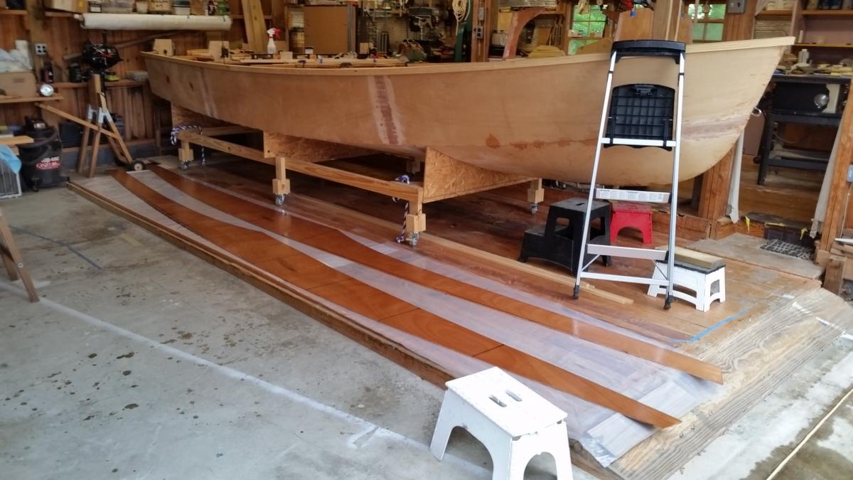
After a two-day 60th Reunion with "brother rats" from the Virginia Military Institute, Class of 1956, in Lexngton, Virginia, I'm back to having fun and progress with "Chessie." The V. M. I. "Color Guard" and Corps of Cadets at parade honoring the returning alumni. After dry-fitting sheer strakes, cabin knees, and the framework for the hatches and companionway -- notes were made and all was disassembled. A list was made of at least a dozen things to be done before reassembly and "tac welding" everything. Such as epoxying all "inside" surfaces, etc. Because the work had to be done on the floor, the hardest job was applying epoxy to the 20'+ sheer strakes. For those who haven't done this yet: Eight squirts each of epoxy & fixer proved to be just right for the 1st coat (applied with a 4.5" roller) covering one side of both strakes AND one side of all four cabin knees. I thought it would take more. Next I'll measure (and post) a fairly accurate square footage of all that was covered. The last epoxy was laid on at 10:45 am. If I can get a "thin-film" set by this evening, I'll apply the 2nd and last coat today. That should end the back & knee-breaking floor work.


-
But the "potti" shelf under the bridge deck is parallel to the WL and the bunk tops, I think?
-
Steve,... Why glass the rudder? It's not under much stress like the CB and several coats of neat epoxy should keep it dry. And an extra coat on the part within the cheeks will keep the sliding parts from wearing through. Also, if you are not sailing and at anchor, it's often raised out of the water. Am I missing something?
-
Core Sound 20 Mark 3 Build - Chesapeake, VA
Pete McCrary replied to AmosSwogger's topic in B & B Yachts Forum
Concerning the photos -- you might contact Frank and he can help with forum problems. Also, when you know the fix, you can edit your post, including its title. You can get your Hull # from Carla. I think they number them as hulls are started as opposed to sale of plans or kits. -
Core Sound 20 Mark 3 Build - Chesapeake, VA
Pete McCrary replied to AmosSwogger's topic in B & B Yachts Forum
Welcome Amos! Nice to have another builder of Graham's Core Sound 20 Mk III. By-the-way, I couldn't open the photos you attached in initial posting. -
Core Sound 20 Mk 3 -- #4 "Chessie" . .
Pete McCrary replied to Pete McCrary's topic in B & B Yachts Forum
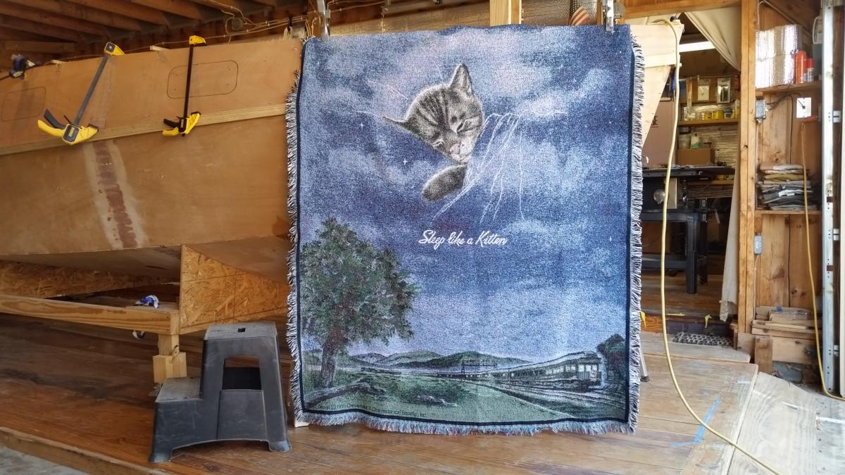
I thought maybe some of you would like to know the inspiration for my choice of "Chessie" for the name of CS20.3 #4. So, here it is (the C & O RR mascot): This afghan will keep me cozy-warm when crusing the Chesapeake Bay and other friendly waters. Just as an aside, in 1966 myself and family (wife and children (2 mos, 2, 4, & 6 yrs)) traveled by rail from Boston to Oakland. Then by DC-6 to Kwajalien Island. We had two connecting rooms and the trip was thoroughly enjoyed by all. There were lots of volunteers to baby-sit the little one while the rest of us enjoyed the dinning car. We returned by rail and later made another transcontinental round trip thru Canada (CP RR) from Montreal to Vancover.

-
Core Sound 20 Mk 3 -- #4 "Chessie" . .
Pete McCrary replied to Pete McCrary's topic in B & B Yachts Forum
Today I made up the companionway frame from Blk 1 to Blk 3 with a pair of stringers and cross-beams at Blk 1 & 2, fwd knee, and aft knee. The spaces for the companionway hatch, its garage, and the fwd hinged hatch (on which the solar panel will be mounted) are nice and square. All this was "dry-fitted." Next I'll disassemble it all, including the sheer strakes and prep all inboard surfaces with two Coates of epoxy. Then reassemble, and tac weld. When all is right: filleting, glassing, and pre-coating. Pretty soon I'll be putting on the cabin roof. This is fun.


-
Core Sound 20 Mk 3 -- #4 "Chessie" . .
Pete McCrary replied to Pete McCrary's topic in B & B Yachts Forum
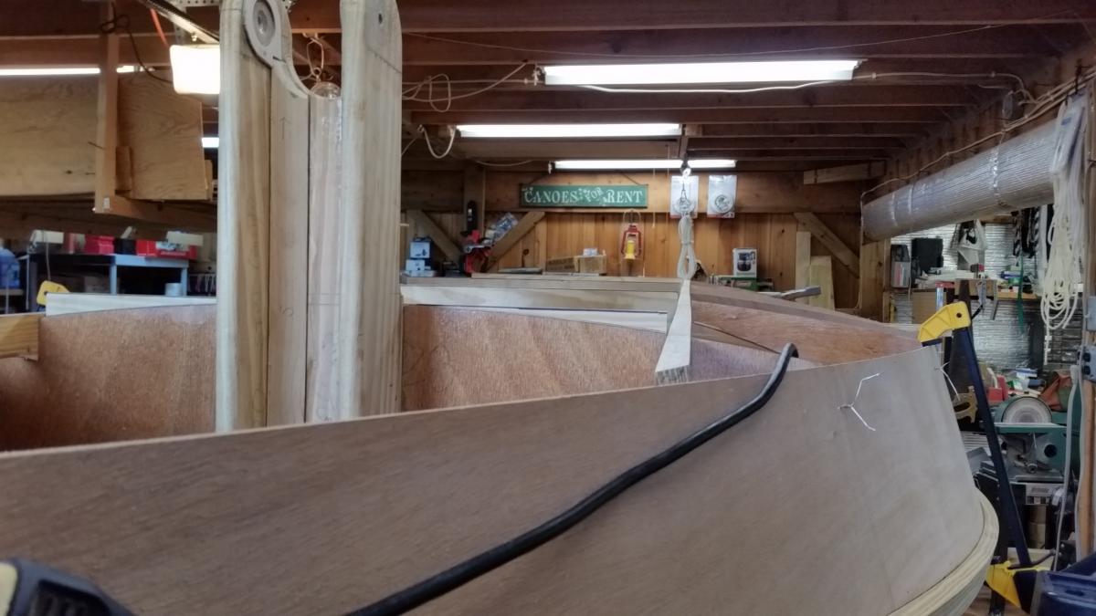
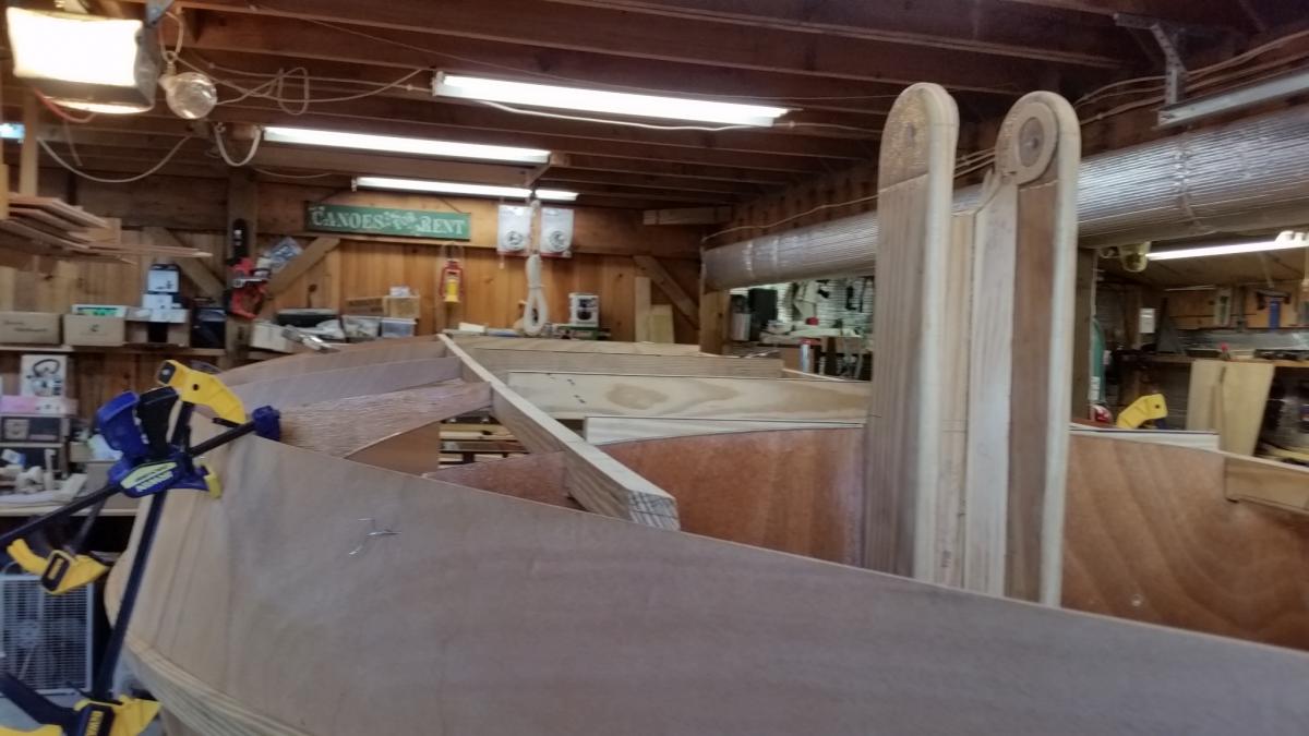
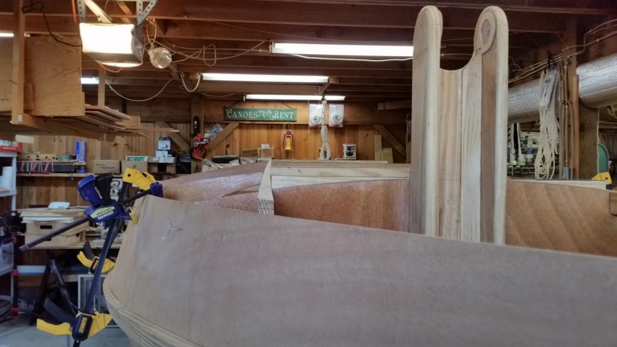
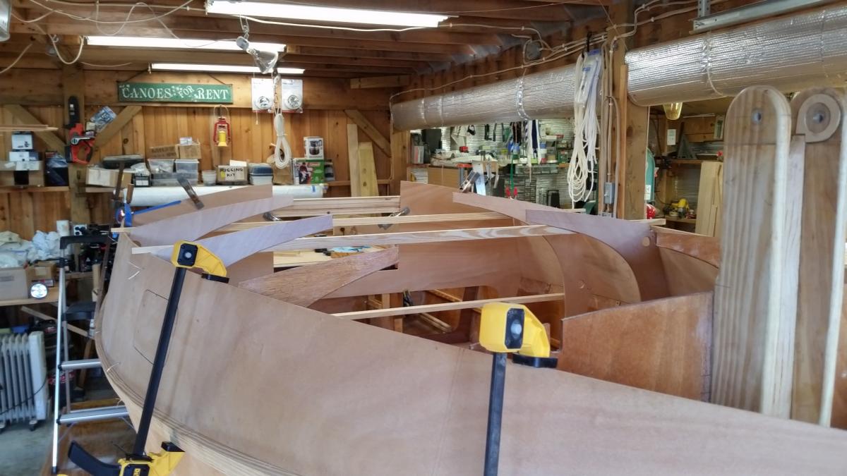
Getting close to looking like a real boat. Not far from turnover. Blk 1, 2, fwd & aft knees, and Blk 3 -- all line up pretty well. Looking aft port side then starboard side. Some trimming will be required, but not much to make true the cabin roof support and companionway framework. Next will be the deck beams and longitudinal rails supporting the cabin roof, companionway, and hatches.


-
Here's a similar approach for the same engine on the transom of "Chessie," a CS20.3: http://messing-about.com/forums/topic/9758-motor-mount-suzuki-25-cs203-4/ The CS20.3 has a forward tilt to the transom. To keep the motor shaft perpendicular to the waterline and allow for reversing rotation, I needed to mount the motor a couple of inches aft of the transom top edge and build-in an opposite tilt [on the bracket]. Note also that the Suziki shaft already has a built-in ~ 5 degree tilt (at its minimum tilt setting) which about doubled the transom "tilt" problem. When mounted, the engine's "cavitation" plate is just below the boats bottom. I designed my bracket so that it can be removed.
-
Would clear & straight yellow pin be an appropriate material? I already have two 22' x 1.5" x 3/4" pieces that I used as battens to make "fair" the side panel / sheer strake joint.
-
I saw an orange tabby in your shop -- and wondered how my "Lucy" got there. But upon checking, she's nearby sleeping. You must have her twin.