Pete McCrary
-
Posts
692 -
Joined
-
Last visited
-
Days Won
40
Content Type
Profiles
Forums
Events
Everything posted by Pete McCrary
-

Core Sound 20 Mk 3 -- #4 "Chessie" . .
Pete McCrary replied to Pete McCrary's topic in B & B Yachts Forum
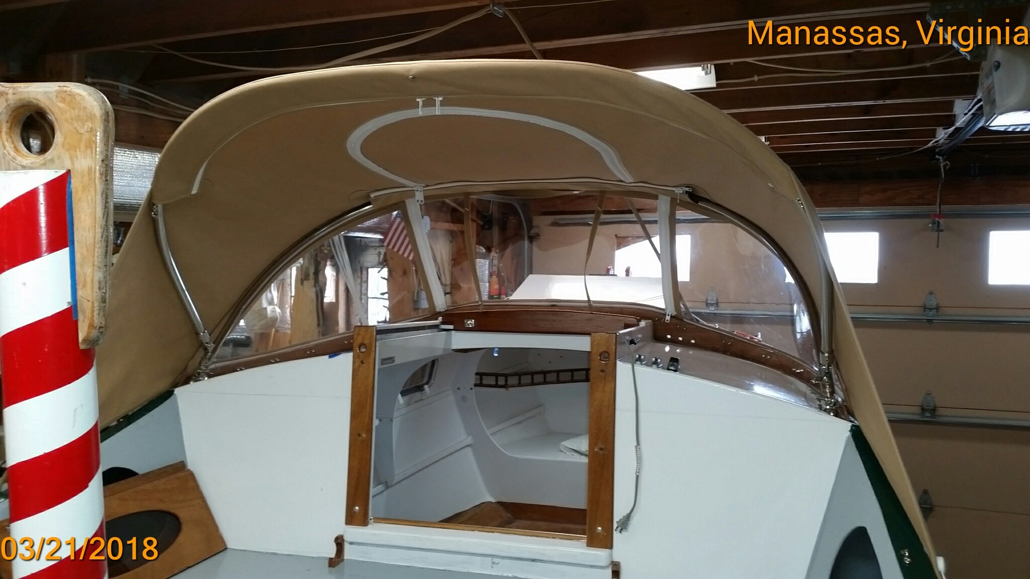
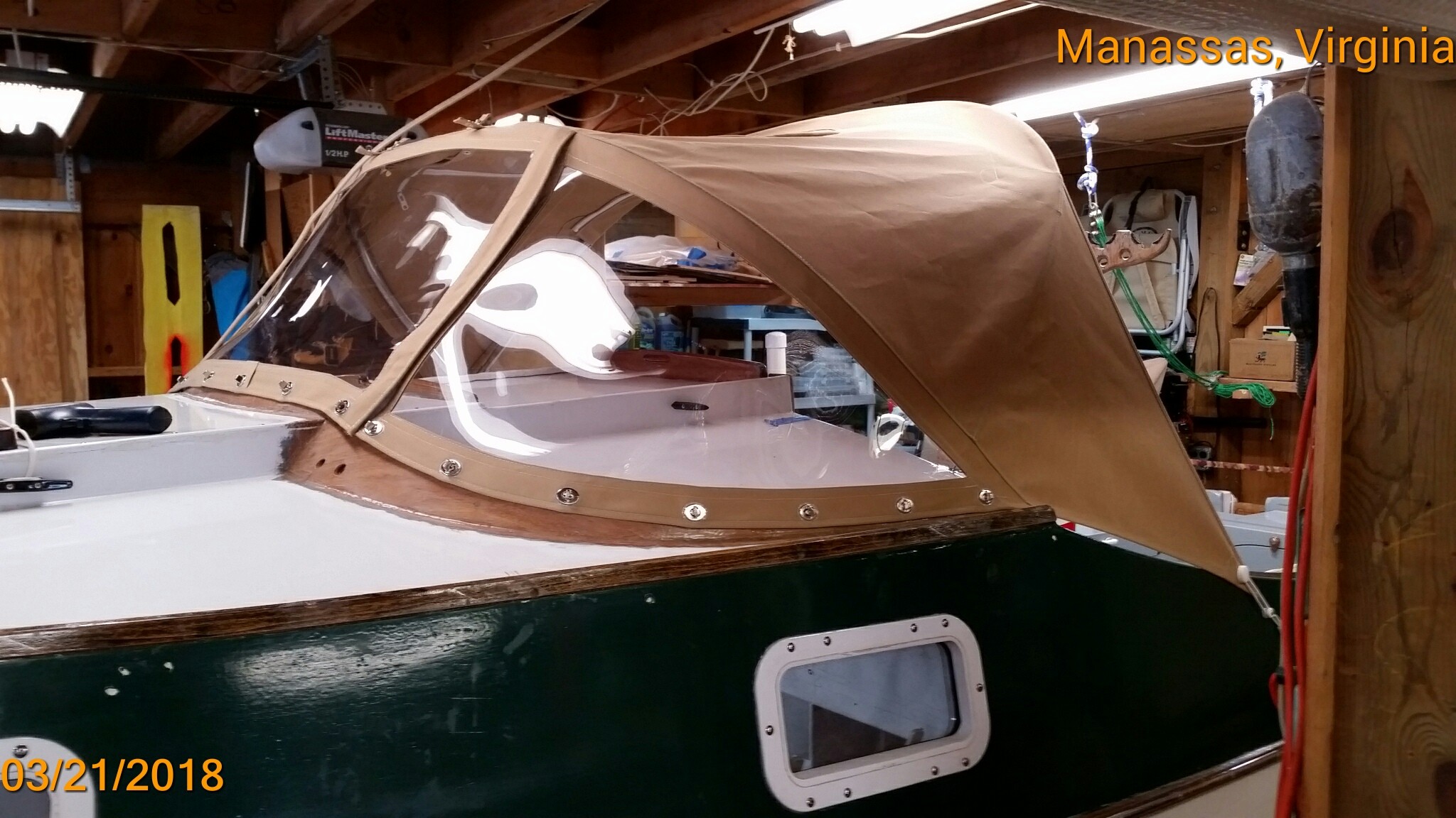
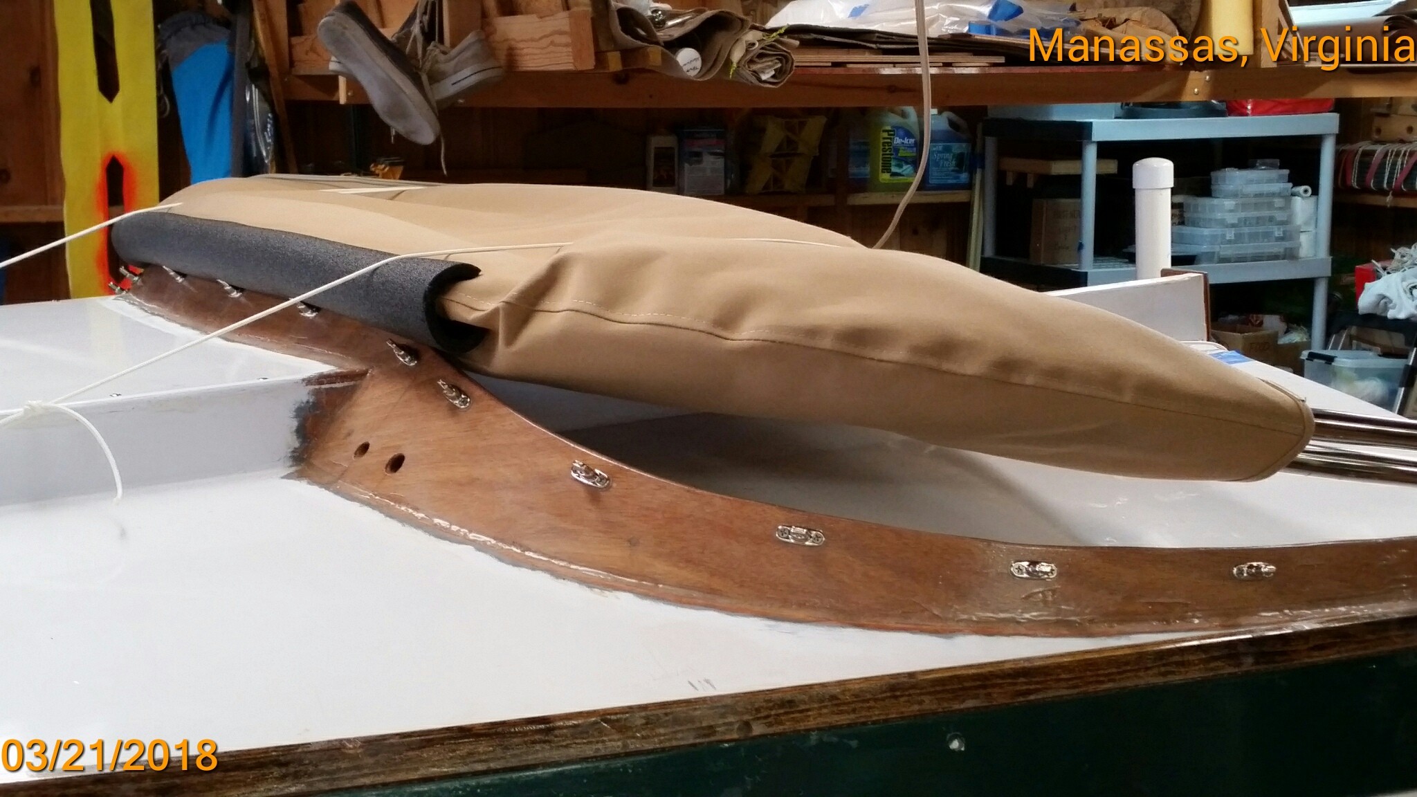
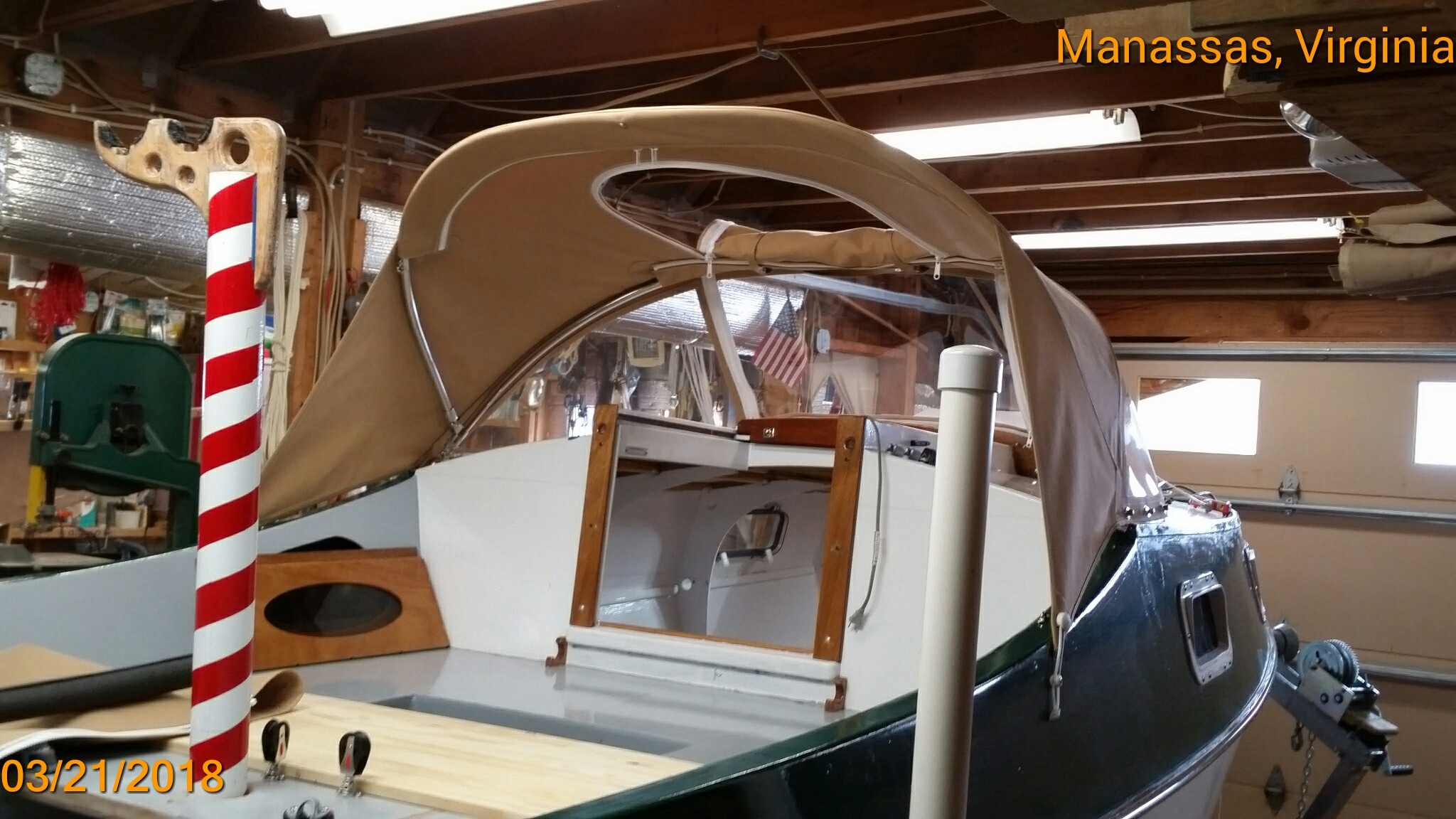
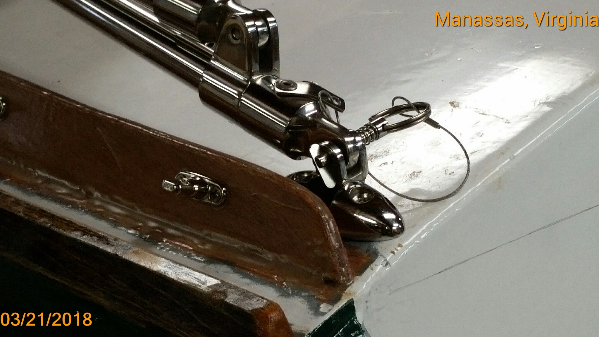
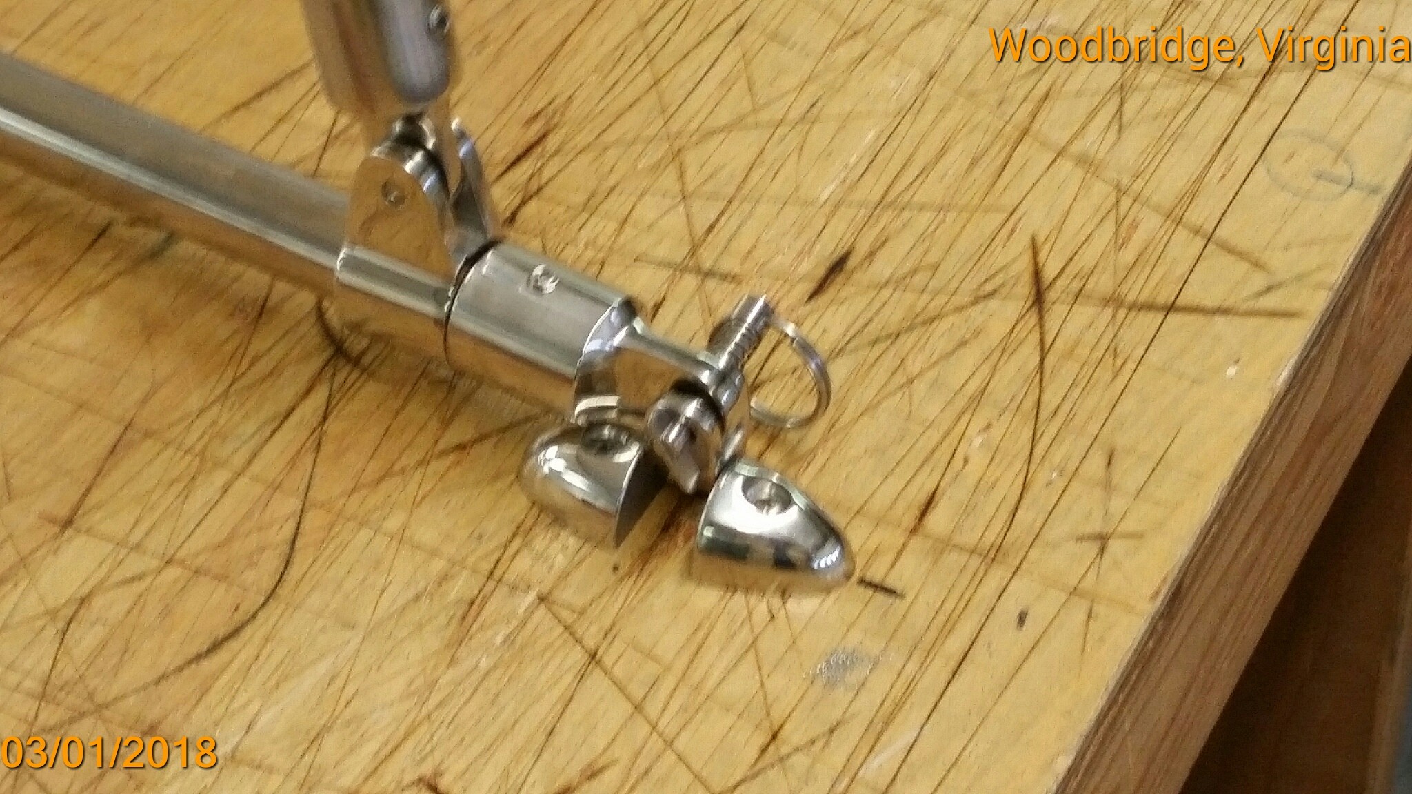
Chessie now has her Dodger and is tucked snugly away in her garage just as Virginia gets ready for the last [hopefu;;y] snow on the 2nd day of spring. Just before Dave (Potomac Canvas Co.) started cutting canvas, I stood under the dry-fitted tubing and decided that the headroom [under to tubing] wouldn't be enough for me to stand in the companionway and comfortably use a hand-held urinal. So I asked Dave if he could cut me a "zippered" opening in the top that would give me unlimited headroom while standing on the cabin sole. He wouldn't guarantee it to be waterproof, but we decided that it would resist all but the hardest rain. And if the companionway hatch is closed, leaking wouldn't matter anyway. And, after final assembly, we discovered another reason to have the opening. It allows for deployment / stowage of the Dodger while on the water. I suppose that will be occasionally useful, but for the most part I'll probably sail with the Dodger deployed. I'll discover if that's the case during this summer's cruising season. Dave originally didn't recommend that the Dodger (even in stowed position) be on the cabin roof while trailering on the highway. But he made a "dust cover" for me anyway. And seeing how well it's secured on the cabin roof, he thought highway travel would be OK. In fact I hit 60 to 70 mph while trailering her home from the canvas shop without any problems. Here are a few photos: The planned "sky-light": The next two photos show the "Boot" -- which we originally called just a "dust cover": The black item is simply a piece of pipe insulation slipped over the leading edge as "chafe" protection where the canvas and tubing rest on the dodger's coaming. Entrance / exit thru the companionway hatch is slightly impeded when Dodger in stowed position.. View from the starboard-side helmsman position. I'd say the view is not significantly impeded. Skylight open and rolled up. View from aft, starboard and port. View from forward and closeup of attachment hardware. Once folded and in the "boot" the whole thing can be removed by just lining up the retainers and pulling the pins. Later, I'll post the weight of the whole thing. NOTICE the wrinkles in the top. They will be "tensioned" out when Dave sends me the "tensioning" straps which will pull the top "tight" with extra leverage much more so than the little bungee cords on the ear-flaps. The first straps wouldn't release easily. By-the-way: The skylight allows one to reach all the turn-buttons while standing on the cabin sole. Absent that feature, deployment and stowage would have to be made on shore before launch. With the skylight open -- I can launch with the Dodger in its boot and strapped to the cabin roof for road transport. Perhaps not deployed at all during a day-sail, or only at anchor (on an overnight cruise).


-
Core Sound 20 Mk 3 -- #4 "Chessie" . .
Pete McCrary replied to Pete McCrary's topic in B & B Yachts Forum
Yesterday checked progress on the SS framing bows and hardware. Canvas work starts after this nor'easter ends sometime tomorrow. The Washington area has pretty much shut down (federal government and schools) expecting wind gusts 50 to [even] 70 mph.


-
A dodger for a Core Sound 20 Mk 3 . .
Pete McCrary replied to Pete McCrary's topic in B & B Yachts Forum
That's basically the same advice given [me] by Dave (Potomac Canvas Co), my dodger fabricator. Thanks for the timely comment. -
A dodger for a Core Sound 20 Mk 3 . .
Pete McCrary replied to Pete McCrary's topic in B & B Yachts Forum
Chessie is at the canvas shop and we have a contract for the dodger. After discussions with Dave, we decided on the following: ^ The canvas will be attached to the coaming with "turn-buttons." The attachment hardware [the male part] will be thrubolted to the edge of the coaming with machine screws, washers, and [on the aft side] acorn nuts. If necessary, they could be removed for repair or repainting the coaming. ^ It will be possible to easily fold the dodger forward to the cabin roof while under sail. To prevent chafing of the canvas and [the] coaming (by the collapsed tubing) chaffing gear will be added to the pressure points. ^ Dave strongly suggested that the dodger not be mounted (even in its collapsed position) while trailering on the highway. He was not confident that a boot could be made that would effectively hold seady and protect the assembly at highway speeds (occasional 70 mph + headwind). Alternatively, he explained that the whole assembly could be easily disassembled. The canvas is attached to the tubbing with zippers, and to the coaming with turn-buttons. And the tubbing assembly is removed with just a pair of pins. To remove the whole assembly -- one needs only to remove two pins and the turn buttons on the coaming. He will make a "dust cover" for the assembly, and it can be stowed in the cabin or cockpit when trailering or [in off season] my garage attic. This will save the cost of a boot made of expensive Sunbrella. ^ We are considering a way to "tension" the dodger when deployed. Usually that's done by attaching the canvas "ear-flaps" to the outside of the cockpit coaming with snaps or other means. We wanted the tension to be adjustable to account for stretching of the canvas over time. To keep the hardware to a minimum I've suggested the following design concept: That's about it for now. Next week I'll approve the fabrication of the tubing and location of trhe webbing guides. After that, the dodger should be completed by sometime in early March. Photos will be posted.
-
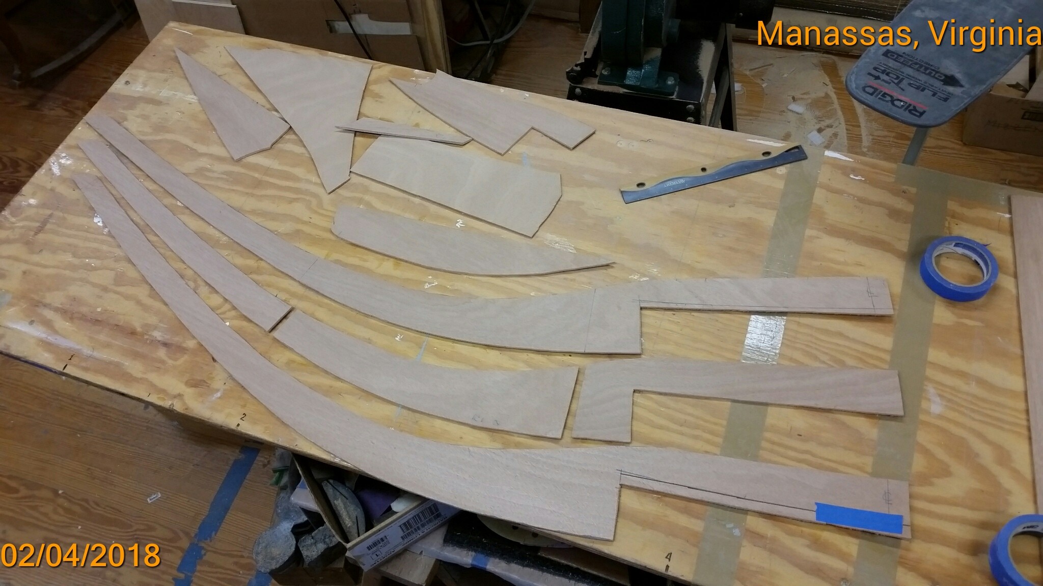
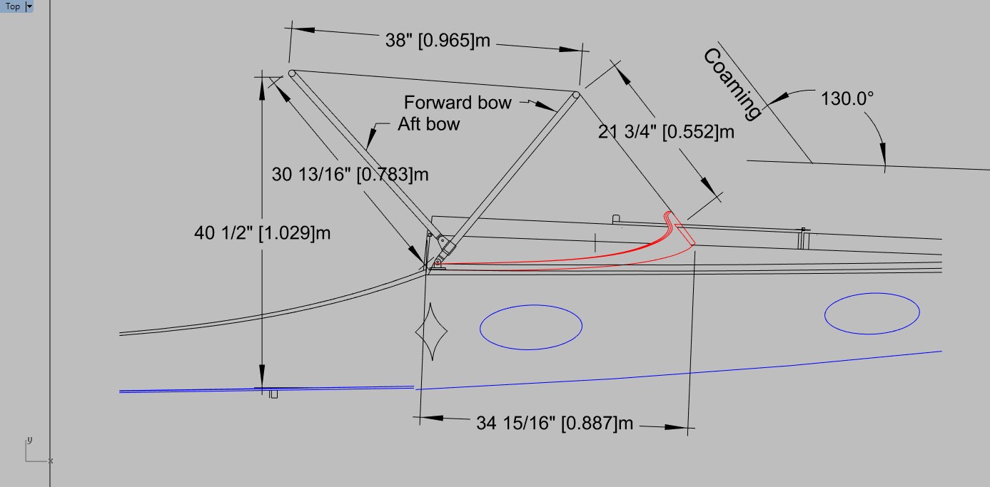
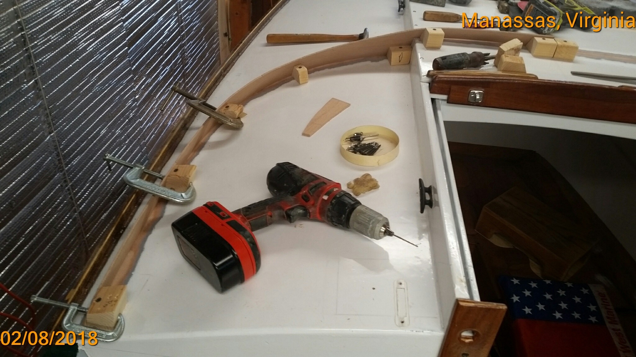
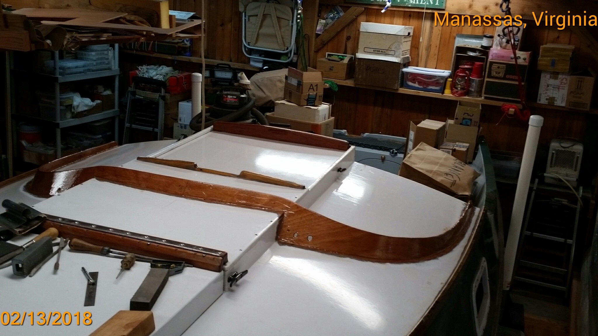
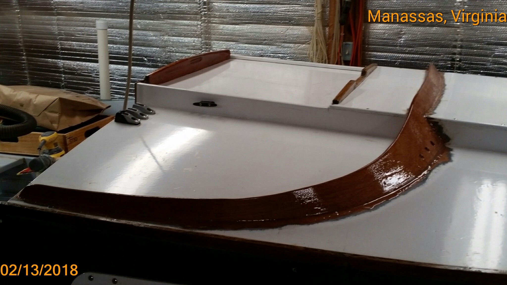
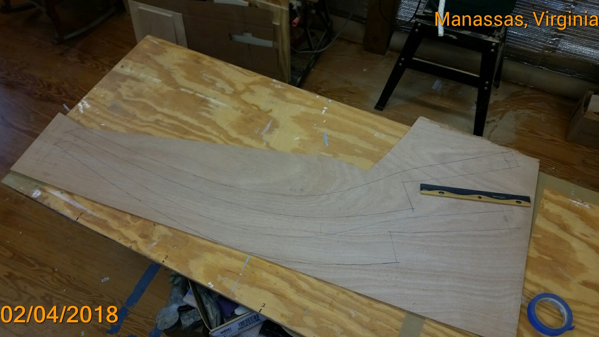
This dodger may be the first for a CS20.3. Perhaps Dough or Jay has one for their boats, but I haven't heard of it. I've admired Graham's dodger installed on Carlita, his CS17.3. To me, it seems an essential item for a cruising boat. Here I'll record the details of the modifications required and its installation. Here are a couple of pixs of Carlita's dodger. Graham provided dimensional drawings for a dodger to fit B & B's CS20.3 design. He also sent full-scale drawings (on Mylar) of the coaming pieces and location on the cabin roof and sliding hatch garage. I marked the outlines on 4mm marine ply with carbon paper. Once cut out, they fitted very nicely to the cabin roof. Notice the second laminate is made up of multiple scrap pieces. The position on the cabin roof was marked with an awl through the Mylar pattern. The B & B drawings also specified the angles (130 degrees over the garage and 8 degrees from plumb at the cabin bulkhead (Blk 3). Using these angles, blocking was cut against which the coaming pieces could be held while the thickened epoxy cured. The coaming was held in place near the front with "#6 washer-hex-head 3/4" screws and clamps on the straighter part near Blk 3. The coaming was first "tac-welded" in place. Then the second laminate of 4mm ply was cut and fitted up against the aft side of the first laminate. I didn't have enough large pieces of 4mm, so the second laminate was made up of several scrap pieces, 3 on the port side, and 5 on starboard. After the first laminate was completely glued up and filleted (epoxy cured) -- the second laminate was glued with generous application of thickened epoxy and held in place with all the spring clamps that I had in the shop. The above pix was taken just after the tac-welding had cured. Before applying two coats of neat epoxy I cut the holes for the mast lines coming aft. Three are needed on starboard and two at port. The larger one on the port side is for two reefing downhauls. They share the same deck pulley and cleat because only one line is used at a time. Here are photos of the coaming ready for installation of the dodger. Chessie will be trailered to the canvas shop tomorrow morning. It's my plan to discuss the following features with Dave, the canvas guy. 1. It should be easily folded down to the cabin roof while under sail with some means to keep it from popping up in a gust and/or wave action. 2.. It will need a cover of some sort (in its folded position) in order to (a) keep the sun off it while boat is trailered & stowed in the driveway, and (b) also to secure it [the folded dodger] to the cabin roof while at highway speeds & headwinds. 3. It should not be necessary to disassemble [the whole dodger] for road transport. 4. For off-season boat maintenance purposes, the leading and side ages of the canvas should be attached to the coaming so as to make its removal fairly easy. Maybe attached with "button snaps" or "turn buttons". And the canvas top should be attached to the two SS tubes by means of zippers. I'll post photos of the finished product. And make a report of its usefulness on my scheduled cruise with the Shallow Water Sailors on May 4-6 (their 39th annual cruise on the Chesapeake).


-
Core Sound 20 Mk 3 -- #4 "Chessie" . .
Pete McCrary replied to Pete McCrary's topic in B & B Yachts Forum
Just finished the coaming for Chessie's "dodger" -- here are a couple of pixs. Tomorrow Chessie will be towed to the Potomac Canvas Co in Woodbridge, Virginia, to have her dodger installed. I'll start a separate topic to detail the dodger design and installation. Also, last week the B & B kit for a "Two Paw 7" arrived via freight. It was a crate about 4" x 24" x 84" weighting about 100 lbs.. The driver, a very helpful young man, carried it up my 150' driveway and placed it on sawhorses in my garage. I insisted that he accept my $20 expression of gratitude. At the curb I had a small hand truck -- which was inadequate for the purpose. Chessie's tender will be named "Catnip," and I'll start her build on another topic. Catnip was Steve's name suggestion. http://messing-about.com/forums/forum/8-b-amp-b-yachts-forum/

-
Any interest in a Catspaw build? Also featuring rabbits.
Pete McCrary replied to cracked_ribs's topic in B & B Yachts Forum
Pete McCrary here. Yes, I'm very much interested in your Catspaw build. I just received the B & B kit for a Two Paw 7 -- and will start a build on this forum just as soon and I complete the inventory of the kit parts. My Two Paw 7 will be the tender for my CS20.3. -
The Kidde extinguisher I bought [last year from West Marine] for "Chessie" turns out to be on the recall list. They are sending a replacement in time for this year's cruising season.
-
Core Sound 20 Mk 3 -- #4 "Chessie" . .
Pete McCrary replied to Pete McCrary's topic in B & B Yachts Forum
Today I actually started on the "Dodger" coaming. Its shape laid out with carbon paper under the Mylar pattern on 4 mm marking ply. Looks like I need another piece so as to have a laminated 8 mm coaming. I'll glue on each laminate separately. The second laminate will be placed an the aft side [of the 1st] and it should be much easier to glue on. After cutting these out, I'll mark the coaming's location on the cabin roof and garage.

-
Fellow small boaters, alert. Maybe some of you already know this, but a Kidde fire extinguisher may be come useless when eurgently needed. Its plastic handle may break off when you try to activate it. And maybe some other flaws. If you have a Kidde extinguisher, note the year on its bottom and the printed S/Nr on its side and call 855-271-0773 during working hours and they will let you know if it is one that has been recalled. If it is, they will send you a new one and a pre-paid shipping label for return of the faulty one. They will properly dispose of the old one. Here's a photo of mine. There's more Info on this web page: https://www.cpsc.gov/Recalls/2017/kidde-recalls-fire-extinguishers-with-plastic-handles-due-to-failure-to-discharge-and John Zohlen of the Shallow Water Sailors alerted me to this recall.

-
Core Sound 20 Mk 3 -- #4 "Chessie" . .
Pete McCrary replied to Pete McCrary's topic in B & B Yachts Forum
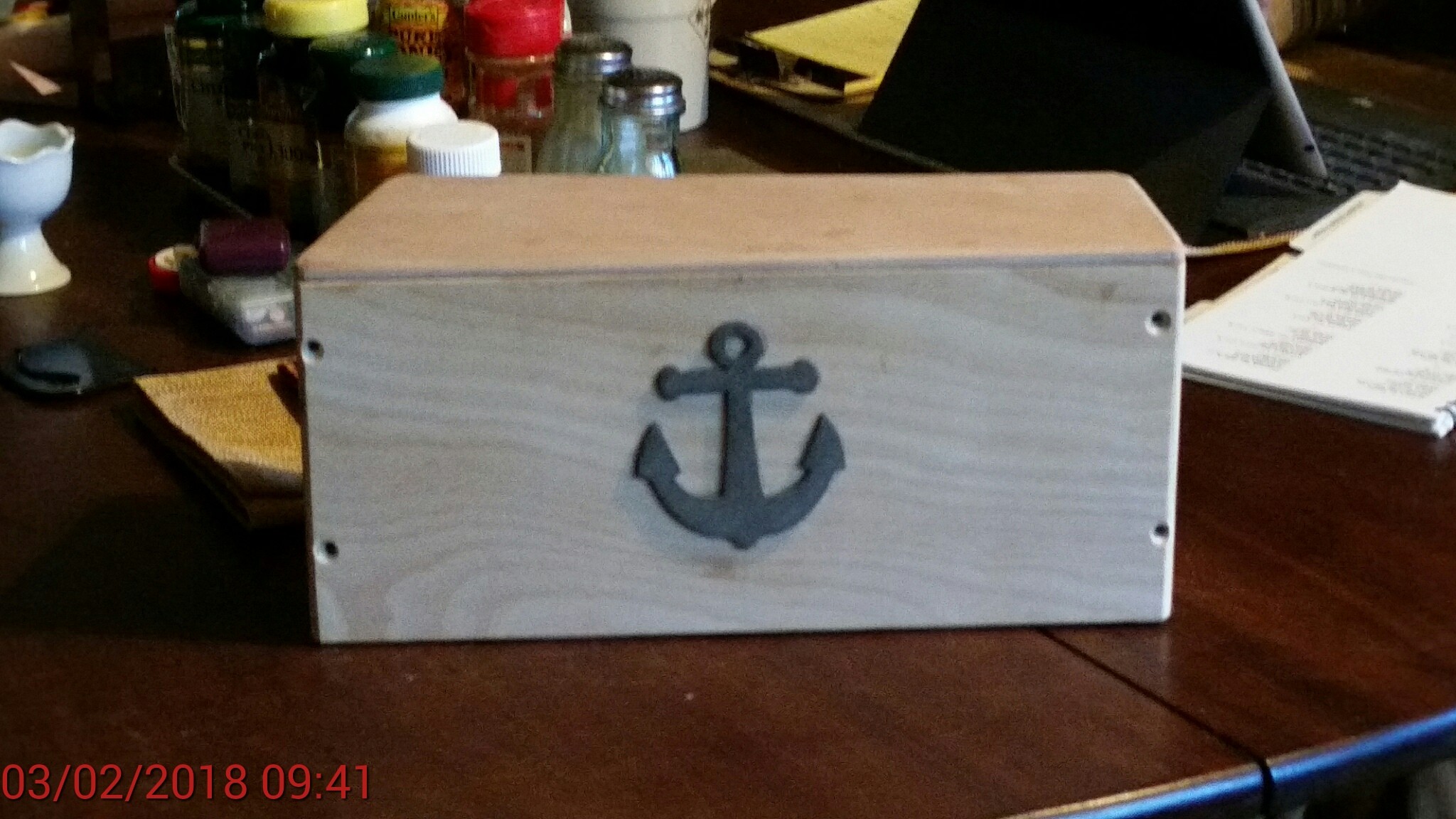
My boat work in December & January has been slowed by cold weather, tax returns, and family events, etc, etc.. But all is looking up at this point. The "Two Paw 7" kit will arrive Monday afternoon. I'm anxious to get started on it, but one more job on the CS20.3 must come first in order to make space in the shop for the Two Paw. That's the coaming across "Chessie's" cabin roof and garage to which the leading edge of the Dodger will be attached. I have all the plans, templates, and materials. Once that's installed, "Chessie" will be moved out of the garage and transported to the canvas shop. While the Dodger is being fabricated and installed, I'll get started on "Catnip," our name for the Two Paw 7 (I think its length is actually 6' 6"). I'll start a separate posting for its build. Then Chessie's electrical wiring and boarding ladder will have me ready for my first scheduled spring cruise with the Shallow Water Sailors (Chesapeake's Madison Bay, May 3 to 6). Non-members are always welcome. Here are a couple of photos of Chessie's "Bunk Box." It goes at the forward end of the cabin sole to support the bunk cushions that overhang the forward edges of the bunk supports. There's easy access to it and provides a "secrete" stowage place for valuables (wallet, keys, etc). The box with closed top. Top removed showing stowage space. That's all, for now.

-
Don,... Before I modified my CLC PocketShip "Tattoo" as a gaff-rigged yawl, I tried to quiet her sailing about her anchor with a jury-rigged sail on a topping lift belayed to the gallows. It had an area of about 16 sqft. Didn't help at all! i haven't yet been at anchor with "Chrssie," but hope she will hold steady with her mizzen tight on the centerline. I could experiment with various reefing arrangements.
-
Bob,... I modified my CLC PocketShip, "Tattoo," into a gaff rigged yawl with a sprit sail mizzen stepped off the centerline at the transom. Before the mod, she annoyingly sailed off her anchor. But she calmed down as a yawl with the mizzen sheeted to the centerline and a tight out haul.
-
Steve,... If you are considering variations on the mast-raising issues -- it may help to refresh your memory by reviewing various post on the subject concerning my problems with "Chessie." Have a look at the various posts on Page 34 (specifically 7/31/17 & 8/3/2017): The final system has worked well for me. It has even survived a potentially dangerous mishap caused my by carelessness (when tired) at the end of a sailing day. The mainmast fell (I was out-of-its-way in the cabin). A loud noise but no damage at all, not even on the sail track which took all of the impact when the mast hit the aft edge of the garage. Just a small dimple on its aft coaming. I made a more thorough report of the incident on my post at Page 35 (specifically my second post for 8/24/2017):
-
Steve,... For my mast light I installed a "deck type" two-pin connector in Blk #1. I can reach it from [standing in] the fwd hatch and can make / break the connection with one hand. But I've had second thoughts on that and may [now] just pass the cable thru a grommet and use a trailer connector -- a two, three or four wire one. You'd probably need two hands to connect / disconnect ... but that would probably be done on the ramp's parking lot. And to make that easier, the connector could be positioned close to the mast rather than the bulkhead. The trailer connectors have proven to standup well to adverse conditions -- being exposed to road dust, debri, salt, etc.
-
Core Sound 20 Mk 3 -- #4 "Chessie" . .
Pete McCrary replied to Pete McCrary's topic in B & B Yachts Forum
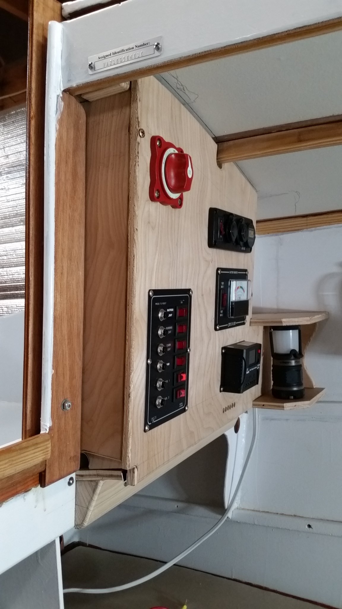
Chessie's electric panel has been fabricated in final form and dry fitted onto Blk 3. Notice the 6 holes just under the solar panel controller. The controller is surface mounted -- and 3 pairs of +/- wires must come from behind the electric panel and into the lower side of the controller. Four of the wires come with the solar panel and are heavy-duty and (with insulation) are 1/4" diameter, with a +/- pair from the solar panel & a +/- pair to the battery. The installer provides the 3rd pair to the backside of the electric panel (+ to the switch and - to the common strip). There's easy access to the rear of the panel. The wiring will enter/exit at the lower corners. Their flexing (opening / closing) will be mostly a twisting motion. The switch is easily reached from the cockpit. The panel is released for access [to its backside] by backing out the bronze OHWS near the top. The next step is to disassemble the panel and remove the electronics so tha the wood parts may be prepared for priming and paint (probably white). The edge piece near the companionway's frame will be finished bright. After that, all electrical fixtures and outlets will be mounted and the whole thing wired together. Then I'll tackle construction of "Catnip" and the reboarding ladder.


-
Steve,... I've been thinking about your plan to have the solar panel over the garage. You may want to reconsider. Use of the space over the garage (for the stowage of the opened fwd hatch) is essential for raising/lowering the mainmast as well for anchoring and rigging. With the panel on top of the fwd hatch, when [it 's] opened all the way, the panel will need protection from slamming down on the garage roof. That can be accomplished with carefully placed cushions or other limiting measures. If the panel is on the garage, cushioning (or limits) will still be needed -- and the effective top of the garage will be raised at least as much as the panel's thickness. And that will require an increase in the height of the frd hatch cover and maybe its coaming.. I, too, am concerned with the added weight and effort to open the hatch -- especially from standing in the companionway. Maybe there is some mechanical way to reduce that effort. Maybe some phnumatic leverage like used on the back window on my pickup cap? It would have to be able to flex thru 180 degrees instead of only about 110. I can't remember if Graham has installed some mechanical help on Carlita.
-
Steve,... My choice for a distribution panel at Blk 3 was governed mainly by the location of my battery (under the companionway step) and ease of access from the cockpit. Also, its volume seems (to me) not to occupy any useful space. And easy access for any wiring changes. BTY I've installed a battery base and reserved space in the forward locker for a 2nd battery if ever needed. However, I'd hate to give up that space for stowage of cooking pots, pans, etc. On December 11 I posted photos of the "Masthead" light that I planned to deploy on the rare occasions that Chessie would be underway using her OBM. My anchor light choice was still pending. But now, I've changed my mind after a more careful reading of the updated CG Navigation Light Rules. https://www.westmarine.com/WestAdvisor/Navigation-Light-Rules Especially note that "Boats < 40' under power can substitute a single all-around light for separate stern and masthead lights." Apparently, recent changes to the CG rules allow this compromise. Also note that the change should appear to allow (for boats < 40') a single fixture (and all-around white over a tri-color) on top of the mast to serve three functions: 1) sail-only tri-color, 2) motorering alone OR while also sailing, and 3) while anchored. The switching would have to allow all lights to be ON for the #2 option. I haven't figured out the required cables -- probably 4. So, now my plan is to mount a Telescoping All-Round LED Nav Light on the deck edge at approximately Blk 2 location (or perhaps on the sheer strake -- at cabin roof edge near Blk 3). It's maximum height is 50" which would put it higher than the dodger that will eventually be over the companionway. If either furled sail "shadows" the light -- I'll ajust the height of the light and / or the tack (with furled luff). It will be used routinely as Chessie's anchor light -- and rarely as the required night "steaming" light. Commentary would be appreciated. Like Steve, "My skin is thick. Some say my head is too." The masthead light shown (in the 12/11 posting) with its vacuum cleaner cable is now for sale to anyone who will come by my shop or spring for the shipping cost (i.e., nothing for the light itself). Here are links to the telescoping light and mounting hardware: https://www.westmarine.com/buy/west-marine--telescoping-all-round-led-nav-light--13022181?recordNum=6 https://www.westmarine.com/buy/perko--pole-light-bases--P009_277_001_030?recordNum=6 The appropriate base would be the "1045 Series, Round"
-
Core Sound 20 Mk 3 -- #4 "Chessie" . .
Pete McCrary replied to Pete McCrary's topic in B & B Yachts Forum
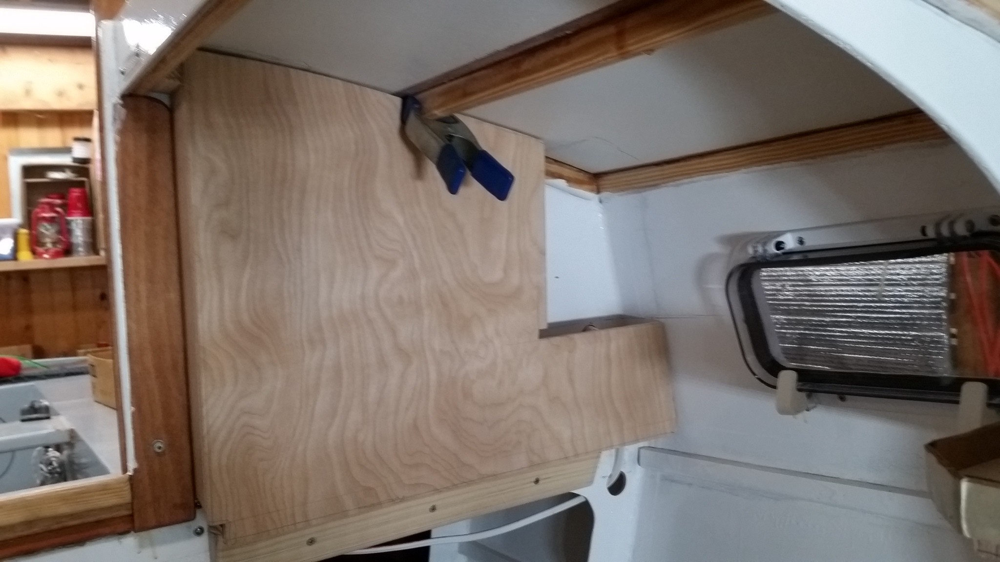
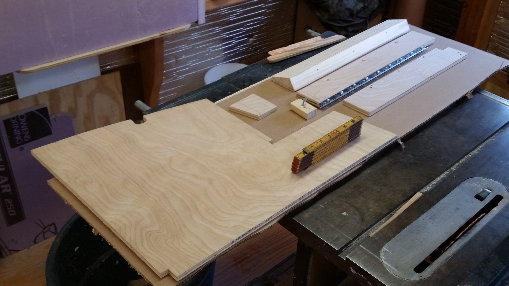
I just finished Chessie's power distribution panel "in the rough." It's mounted on the cabin's port-side of Blk 3. It's assembled and mounted with screws without any need for glue. That way it can easily be modified or completely removed if necessary. The material is all 1/2" birch veneer ply except for the mounting bracket, which is ordinary pine. Although there is no glue -- I will epoxy all surfaces. I chose the port-side because I'm right-handed and working on that side is easier while sitting on the bunk or a stool on the cabin sole. The inside electrical components are accessible by lowering the front panel which is on a hinge. Here is my sketch of the mounting details: The parts are shown here -- except for the shelf. Here the bottom of the panel box has been hinged. The hinged bottom will be screwed to support bracket which is shown alongside. Showing the mounting details. The assembly is ready for dry-fitting it to the support bracket. Notice that the shelf is attached. The support bracket has been screwed thru Blk 3 and into the cockpit deck support cleat. The inboard edge of the panel box has been attached to the companionway framing. Notice the cable coming out of Blk 3. Within the cockpit coaming [on Blk 3] there is a 12 v. socket for shore-side charging of the battery. It is "unswitched" and goes directly to the battery. It has its own in-line fuze. That cable will be covered by the distribution panel. The hinged panel is dry fitted to Blk 3 and the support bracket. Panel lowered for access to cabeling and back-sides of electrical components. Panel in stowed position. Note that shelf is in a high and handy position for a portable cabin light. The light has 3 brightness for white and can be switched to red (one brightness). The red can be switched to blink an "S O S." I'm thinking of painting the panel white to be consistent with the cabin interior. But I might finish it "bright." Later, I'll post a photo showing the electrical components mounted into the panel. Next up will be construction of Chessie's micro+ tender, "Catnip."


-
Nice progress, Steve. When you get to the point of fabricating a distribution panel, check out my build. I just finishes (in the rough) the panel for Chessie with details posted on her "build."
-
This morning I measured the fuel remaining after the Tohatsu 3.5 "check-ride." The actual consumption was 2.9 liters. The corrected performance date are: Fuel rate: 0.6 liters/hr Mileage: 7.24 nm/liter The posting for December 5 has been appropriately edited.
-
Alan's link takes you to a slightly different light than the one Graham and I have. Ours is a tri-light: red, green, and white (white facing aft) and requires just 2 wires (+ & -- 12 VDC). The link model boasts also an "anchor" light (which would be 360 degrees and never be on when navigating) and it would require a separate +12v circuit. The specs state that it has 3 wires -- which would provide the separate anchor light circuit. A really nice improvement.!!! A bulkhead mounted 3-wire plug/socket pair may be hard to find. I haven't seen one, but a trailer 4-wire connector would do fine. The power line would exit Blk 1 thru a grommet to a loose trailer connector on a short pigtail -- then thru a grommet and up the mast. The new one would eliminate [my] need for a deployable anchor light which I plan to hoist on a halyard or topping lift.
-
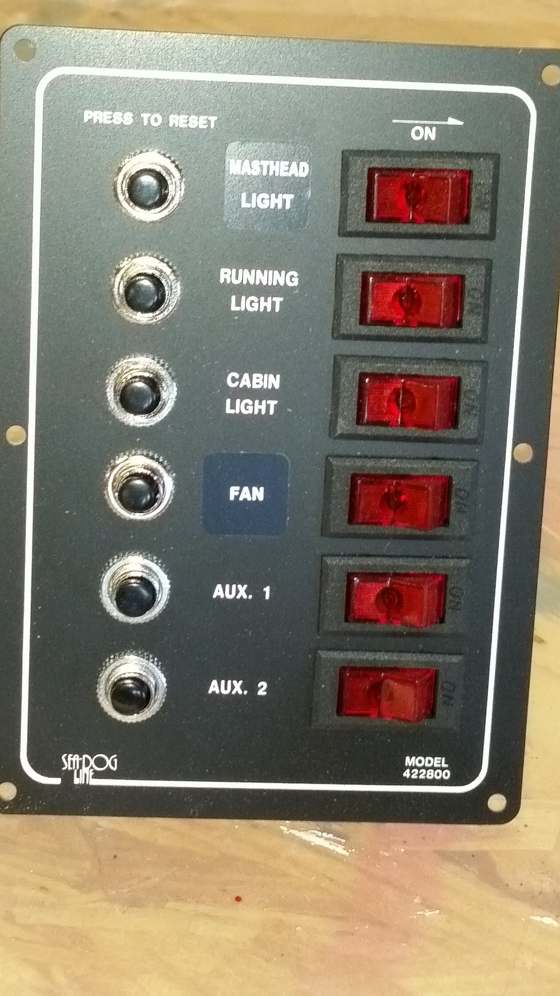
Steve,... I bought the stand-alone volt meter before the other one was on the market. It's good for two batteries if I ever need that. And the other one may (???) also measure the voltage OUT of the USB outlets. This is not clear from the meger instructions. And it's separately fuzzed. Don't know Why! Graham installed Chrssie's tri-light. I don't know the source. BTW, Graham made a slight modification so that it would better fit the top of the mast. I don't know the details of his mod. I managed to measure the current draw for the switch lighting on my SeaDog distribution panel. Here are pixs of the lit switches: All switches on. One switch off. My multi-meter wouldn't close the circuit in its amp meter mode. Probably a blown fuze. Henry's 40 year old Radio Shack meter made the following measurements: 6 lights: 210 ma; 5: 180; 4: 140; 3: 110; 2: 70; 1: 30; 0: no load. All were made on the 250 ma scale. So, that's about 0.035 amps / light. Or, 0.21 amps with all six lit. Wouldn't that mean a 90 ampHr battery would power all six for ~ 428 hrs (18 days)? My guess is that these lamps are LEDs. Anyone know the typical current draw of a small 12 v. LED lamp? I have the feeling that these lamps may not be too bright for comfort at night. Typically only two will be on at night. If too bright, a small curtain should solve the problem. Good luck on finding one source for all electric needs. Prices and details are all-over-the-place.


-
This morning I'm going to see if I can measure the amps drawn by the switch lights. Hopefully, I'll have the newer version. On one boat I had a panel that had a switch that would kill all the lights. Nice feature. And on another one if the master switch was on and no lights showing, there was a small current drain. Dead battery in the spring. BTW, the edit button in at the bottom of the post on the line with the "Quote" button.
-
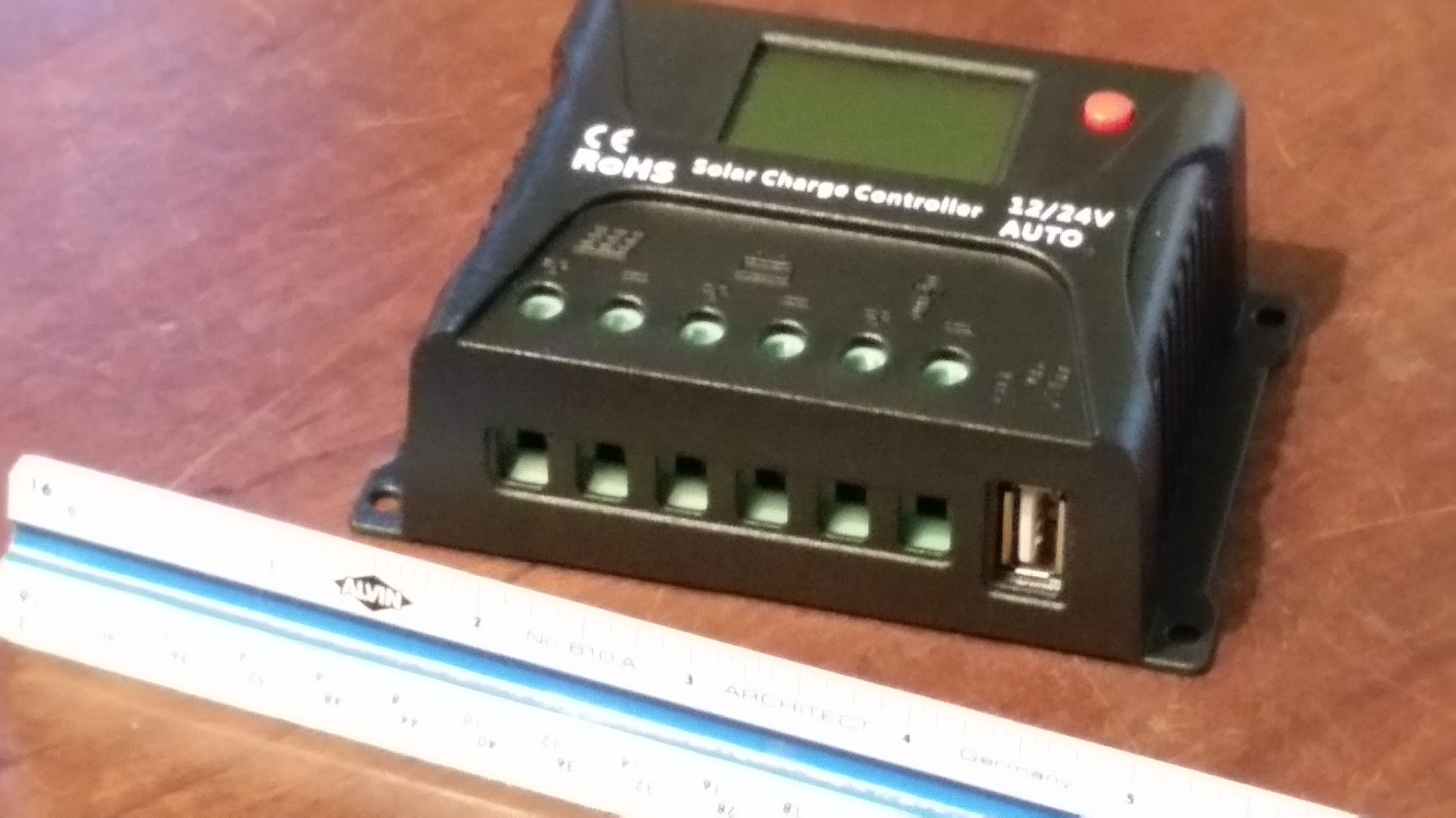
Steve,... B & B installed the LED tricolor on the top of my mast. The electronics is such that it only needs two wires to light up all three colors. I suppose it has some circuitry and polarity arrangement within the light's framing. I've installed a "deck" socket on the starboard side (forward face) of Blk 1 into which is plugged the line that goes up the mast. If you use motor-power at night you also need a "masthead" white light. It should be about 2 meters above the deck facing forward. I'm going to use a "portable" light and flexable cord (like what powers a household vacuum cleaner) that will plug into another "deck" socket on the port side (forward face) of Blk 1. On the rare occasion that I need it, I'll deploy it onto the mast from a position standing in the forward hatch. I'll have a small bracket permanently installed on the forward side of the mast upon which I'll hang the light -- at the maximum height that I can reach. Here are the elements of my electric system yet to be installed: Not shown here is the LED tricolor, battery, battery-charging socket, and the solar panel itself. Here is the masthead light and flexable cord. Breaker and Distribution Panel. . Solar charger control -- notice the USB outlet Power outlets include two USB ports and 12v "cigar lighter" outlet. It is not rated for above deck use. Bunk reading light. The first photo also shows two overhead cabin lights and a two-socket 12v outlet rated for above deck. The two-socket outlet will be installed in the cockpit (probably) under the mizzen partner on the starboard side. The overhead lights will be installed over the forward locker and just forward of Blk 3 (port-side). The electric panel will be on the port forward side of Blk 3. It will be on a hinge so that it can be rotated down to a horizontal position for easy access to the wiring. Not shown is a "deck" socket on the aft side of Blk 3 inside the cockpit coaming that has its own in-line fuze going directly to the battery for on-shore charging. The fan is a "low-drain" two-speed -- and very quiet. I've used that model on two other boats and like it very much. I'll probably install it on the ceiling near Blk 2.