Pete McCrary
-
Posts
692 -
Joined
-
Last visited
-
Days Won
40
Content Type
Profiles
Forums
Events
Gallery
Everything posted by Pete McCrary
-
About the forward hatch position — I’d keep in mind that the reefing pendants (I recall only 3 {or 4?} for the shallow reef) need not be tied immediately in order for the reefed sail to have the desired effect. They function mainly (on a loose footed sail) to tidy up the sail’s foot and reduce windage. They can be left loose until all other lines are tended and the helm adjusted for a steady course. The two aft ones can be tied while standing in the companionway — and maybe even a 3rd one (can’t remember for sure ?). I rigged Chessie’s mains’l (as per one of B&B’s drawings) with two reefing downhalls, each with a x2 pulley (on its downhall hook) and both lines reeved thru the a single pulley (on the cabin deck) and the same closed cleat at the cabin bulkhead. They never fouled one another — the one under stress easily shoving the slack one aside. Of course, in order to have the benefit of reefing from the cockpit, one had to remember to hook the right (color coded) line into the right cringle when bending the mains’l at the ramp. I found that the forward hatch (hinge on aft edge) was in the right position for mainly tending anchoring — and the fwd reefing pendants while on the water. Of course it was also essential for raising/lowering the mast. I found it awkward (even difficult) to open the hatch from the inside — so I rigged a strap (attached to the inside of the hatch’s fwd lip, then outside and back to the companionway). But to sail safely with that arrangement you had to contrive a means of latching/unlatching the hatch from the companionway. I simply decided to sail with the hatch held closed only by its own weight. I made it a rule (rarely broken) NEVER to climb onto the cabin roof. For a solo sailor, falling off into the water could easily be a life-ending event. And even with a crew, it would be a major challenge to successfully achieve a rescue. And whether solo or with crew aboard or nearby, a fall of 5’ to the ramp or tarmac would probably result in an injury — even a serious one and perhaps crippling or life-ending. In my 87 years I’ve fallen a few times (from near-zero height) and have suffered injury 3 times — age 12 fell from 3’ fence, broken forearm (both bones) requiring open reduction; age 67 tripped on curb, compound fracture of right pinky; and age 75 slipped on ice, 180 degree extension of left index finger with torn ligaments. The roof on a raised deck cabin (without stanchions) should always be OFF LIMITS !! I’m my humble opinion.
-
Steve, I just re-read [more carefully] your historical note on the June capsize of “Skeena.” And I recall being amazed that the CB cut right thru the hard foam bumper and continued right on to split the top of the CB housing. However, after more consideration, it shouldn’t be quite so surprising. Eighteen pounds of lead at the end of a 4’ leaver-arm, falling in an arc of 90 degrees, will concentrate a tremendous force (at the end of the arc) as it hits the foam bumper. And, you probably tapered the trailing edge (of the CB and lead tip) to a fairly sharp edge. That edge would hit the top of the CB housing like a falling guillotine. No wonder it split. I’D SUGGEST TO CORE SOUND BUILDERS an easy preventative measure: epoxy a 1/4” marine ply to the bottom of the foam bumper. That would spread and absorb the impact, and in my opinion, prevent any damage by a falling CB. The underside of the 1/4” ply should be fiberglassed to insure against it’s shattering. Big impacts can also happen on highways caused by bridge grades not matching approaching road grades — a common highway problem.
-

Spindrift 10, #1329 -- "Seabiscuit" . .
Pete McCrary replied to Pete McCrary's topic in B & B Yachts Forum
I think Dave has it right. If you want to separate the tubes for transport, you'd never insert the tubes while any epoxy is not yet cured. Dave made his bushings one layer at a time until just a little too big, then sanded down to a proper fit for steadiness and ease of separation. My procedure was to wrap (modestly tight) the smaller tube with FG tape (end secured with masking tape) until the thickness was just the ID of the bigger tube (measured with a "mic") -- then [I would] lay out the FG on bench (surface covered with packaging tape) and wet it thoroughly with epoxy. Then lift it off the bench and wrap it (keeping it taut) on the tube. After cure, the thickness should be slightly more (than measured) because of the epoxy. Then sand to the fit that you want. Worked OK for me. -
Spindrift 10, #1329 -- "Seabiscuit" . .
Pete McCrary replied to Pete McCrary's topic in B & B Yachts Forum
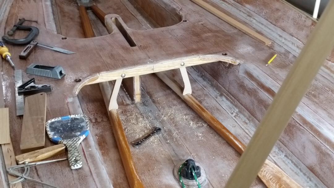
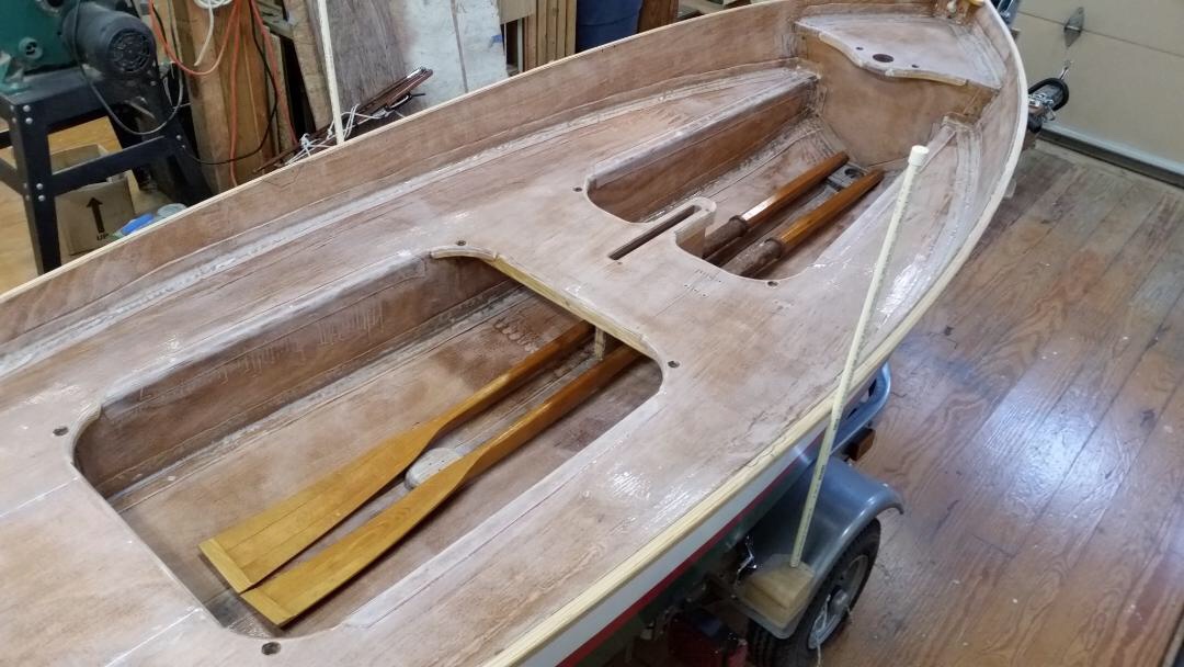
Now that Seabiscuit’s oars are approximately 7’ and can be slipped under her midship thwart, they need to be made secure for road transport and vigorous sailing. So I fabricated a pair of “jam cleats” (? nautical name suggestions please ?) shown here: They’re made of 1/2” maple pivoting on 5/16” carriage bolts each held in place with two 1” ss washers and a nylon lock nut. The nuts allow adjustment “just-so” the jam cleats may be rotated outboard and under the thwart — like this: Notice the stowed starboard-side cleat’s foot just showing under the the thwart’s aft crossbeam. To engage the cleat — it is simply rotated down to the oar, which is manually depressed by about 1/4” as the cleat is slipped over [it]. The final photo shows the oars in place (only starboard cleat engaged) with rudder/tiller assembly, CB, throw cushion, and combination paddle/boat hook — all stowed in the cockpit: With the oar blades flat on the cockpit’s sole, the oars are mostly out-of-the-way and could even provide some “purchase” for the crew when hiking.

-
Spindrift 10, #1329 -- "Seabiscuit" . .
Pete McCrary replied to Pete McCrary's topic in B & B Yachts Forum
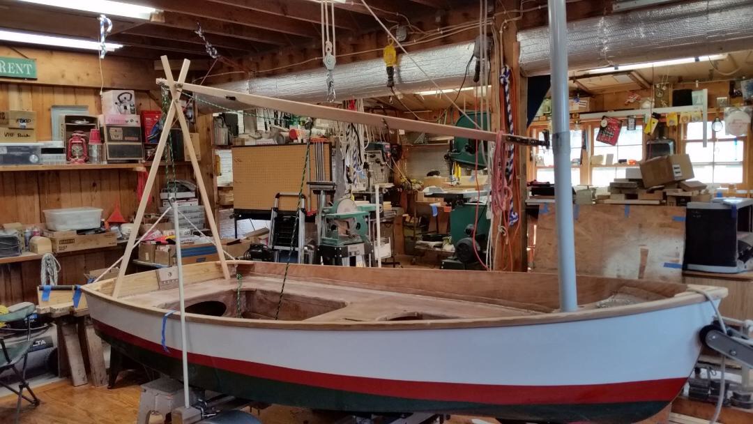
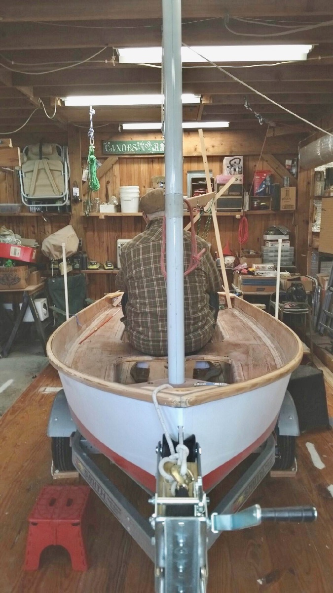
Suppose you’re sailing your Spindrift 10 nicely and the wind just quits. No problem, you think. After all you’ve brought along a pair of oars. But the boom and ferruled sail are now in the cockpit and seriously in the way. Repurpose the halyard into a topping lift? Yes, but to keep the boom from flopping around you sheet it in — then the sheet is in the way, hindering easy rowing. So, I conceived of a “boom jack” — weighing just under a pound and easy to stow in the bottom of the cockpit. It can hold the boom (with feruled sail) on the boat’s centerline at a height above the rower’s head, or lower, but to either side above his shoulder. It’s just two sticks arranged like “scissors” and held together with a carriage bolt and wing-nut. Here are proof of concept photos: The geometry is stable, the X of the jack held against the cheek block and fairlead near the end of the boom. Especially when the boom is tensioned down with the sheet. Quarter inch plywood “dogs” glued to the seats will restrain the bi-pods from slipping. Boom-jack collapsed. Note the 2nd hole in the top leg near its center. That is used to make the bi-pod asymmetric — holding the boom to one some or the other. Skipper’s choice. Boom jack, stowed. Jack made to be asymmetric, showing boom to port over the rower’s right shoulder. From this perspective the boom looks close to rower’s head, but it’s actually at a comfortable distance. I’ll have to wait for warm weather to try an on-the-water deployment. Report to follow. Comments and suggestions welcome.


-
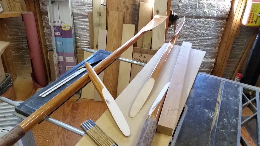
It all went quite well — not nearly as difficult as expected. Here are a few pixs: Notice the two indexing 2” x 3/32” D finishing nails. They were easily pulled out about 5 hrs after glueing but before an overnight cure. After clamping they were removed from the (unheated) shop to our dining room table. It’s nice to have a tolerant wife. The next morning. Back in the shop. Nice and straight, but the starboard oar is like 3/8” longer — and I won’t let it bother me. QUOTE from earlier: “Which reminds me: Don't forget to slip the closed oarlocks onto the shafts before gluing up the scarfs!” I forgot anyway! Remembered last night just before falling asleep. So, off with the glued-on buttons — or, like the other pair that went with the Penobscot 14, I’ll cut a slot in the top of each lock, slip them over narrowest part of their shafts, and close the oarlock’s tops with lashings. Each oar clears the transom. And the aft seat. The blades lie nice and flat and won’t seriously hinder movement in the cockpit. See the misalignment of the scarf on the edge towards the oar blade. That’s the result of the shaft being slightly tapered. I’ve positioned the two pieces so that the difference is minimal near the leathers — which leaves most of the trimming to be done towards the blade, consistent with the designed taper. You may notice a horizontal line that looks like a “glue line.” It isn’t. The line was scored on the centerline of all 4 sides of the original 2” x 2” stock — as a guide for 8-siding (and rounding). As tapering progressed, the scoring was redone to keep it visible. One nice accidental of the scarfing is that the oars will be a little lighter outboard of the locks.


-
That would be a lot more trouble (in my opinion). Also, it would shorten the 8-sided part of the oars inboard of the leathers and require relocating the leathers. That would then show the shaft (that's inboard of the [relocated] leathers) as part 8-sided and part cylindrical. And the shaft outboard of the [existing] leathers is tapered -- complicating the installation of new leathers and altering the designed balance [of the oars]. The existing leathers and buttons would probably be ruined by their removal (they were attached with copper tacks). Which reminds me: Don't forget to slip the closed oarlocks onto the shafts before gluing up the scarfs!
-
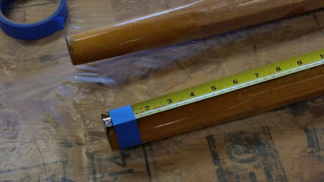
Actually, two saw cuts. And some of the error could be a messy measurement.
-
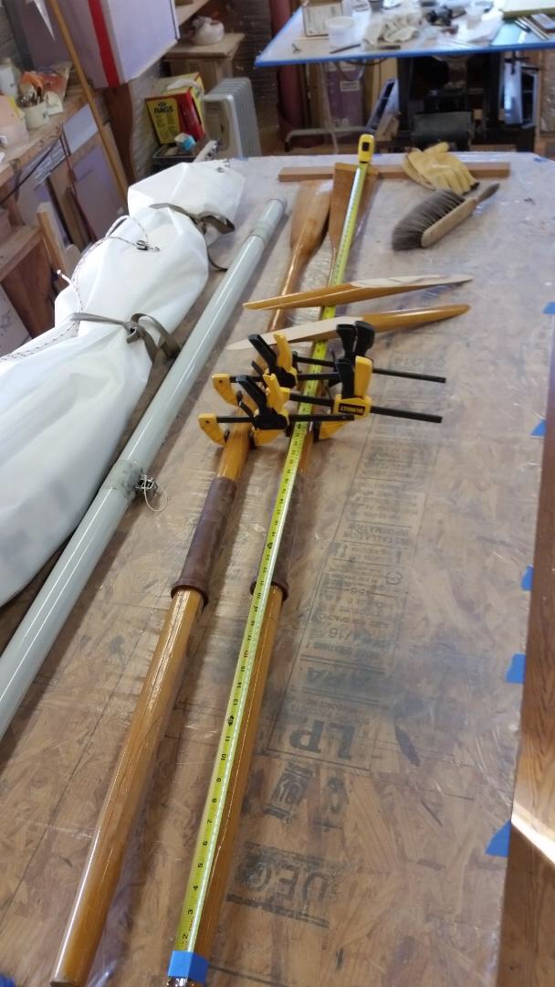
About 15 years ago I made two sets of oars to use with the Penobscot 14 that I made. Each pair were made of three 8’ lengths of 2” x 2” (actual cut dimensions) Sitka spruce, the third length was cut into 4 two foot lengths for the blade. Wonderful to row with. When I sold the boat last summer, I let a pair go with it and kept the other [pair]. But they’re too long and won’t slip under the midship thwart of Seabiscuit, my Spindrift 10. A cheap 8’ one-by-four proved that a 7’ 1” oar would be OK. So I got up my nerve to make two 8/1 scarf cuts into each of my beautiful oars. Fortunately I already had a rig that I made to cut tapered table legs years ago. Here are a few pixs showing the rig and cuts: Wouldn’t even fit between the fore and aft bulkheads. Much less slip under the midship thwart. Bottom side of the scarfing rig. Both table saw top and rig bottom were rubbed with bees’ wax. After the cuts. For the cut the oar shaft was clamped to the 2 x 3 which was set for an 8/1 cut. The first cut was started just near the leathers. For the second cut the shaft and rig were both marked and then the shaft moved up exactly 12” for a 12” shorter oar. Error! Resulting in a 13” shorter oar. Forgot to account for the saw “kerf.” Elongated at that! Dry-fitted — they line up nice and straight. While dry-fitted in perfect alignment, I’ll index [each pair] assembly with two wax-coated finishing nails — so they won’t slip from alignment during the glueing process. When finished I’ll post photos of the shortened pair.


-
Checklists !!! Where forgetting is fatal, they are a requirement. Flying an airplane, scuba diving, etc. Also where forgetting is expensive — like loss of boat, big repairs, etc. For Chessie I had a checklist for approaching the dock, hauling out, making rig “road ready,” etc. Kept it in my shirt pocket for easy reference. Also one for rigging and launching. They are especially important at the end of the day when you’re tired (even exhausted). Also at start of day when you may be in a hurry to get under way — or distracted by “helpful” bystanders. Even with checklists, I’ve forgotten important steps — and Lady Luck has often saved my butt.
-
Steve! What a frightful experience. Totally upside down! But your recovery was really amazing. If you had ballasted her do you think she would’ve gone over? I thought the hollow masts would’ve provided enough floating torque to prevent her from going bottoms up. Glad you and Teddy are safe.
-
Spindrift 10, #1329 -- "Seabiscuit" . .
Pete McCrary replied to Pete McCrary's topic in B & B Yachts Forum
Joe,... Not really sure. Maybe a couple of reasons: just to have a clear midship thwart, or perhaps because one of B & B’s drawings showed it on the keel. Really should have waited until after a few hours of sailing in various conditions. But I can always relocate the cleat. Maybe tryout both locations. And I like the elliptical shape of the white oak base — plus I had a scrap piece just the right thickness. Also, I love the conic sections upon which our plywood panels may be bent into neat boats. I especially like the ellipse which may be easily drawn. Below is the sketch I generated for the cutout pattern. You just hold the string firmly at each foci and (with a pencil keeping the string taut), rotate the pencil & string — marking the profile of the desired ellipse. Besides, I really like messing about in my shop.
-
Spindrift 10, #1329 -- "Seabiscuit" . .
Pete McCrary replied to Pete McCrary's topic in B & B Yachts Forum
Same location on the boom. Might move it a little aft. I’ll probably wait‘till after a season of sailing. -
Spindrift 10, #1329 -- "Seabiscuit" . .
Pete McCrary replied to Pete McCrary's topic in B & B Yachts Forum
The clam jaws are kept lined up with the sheet because the jaws rotate on swivel (vertical axis) which points the jaws directly to the skipper pulling on the sheet — and the sheet from the boom is lead into the jaws by a fairlead which is directly over the swivel’s axis. A photo showed it much better. Here’s a link to one (that is for a larger diameter sheet): https://www.ebay.com/i/293543787196?chn=ps&norover=1&mkevt=1&mkrid=711-213727-13078-0&mkcid=2&itemid=293543787196&targetid=4580977766998583&device=c&mktype=&googleloc=&poi=&campaignid=403204665&mkgroupid=1238050308086972&rlsatarget=pla-4580977766998583&abcId=9300377&merchantid=51291&msclkid=9636e260221f15b9034abda7c643a3f3 -
Spindrift 10, #1329 -- "Seabiscuit" . .
Pete McCrary replied to Pete McCrary's topic in B & B Yachts Forum
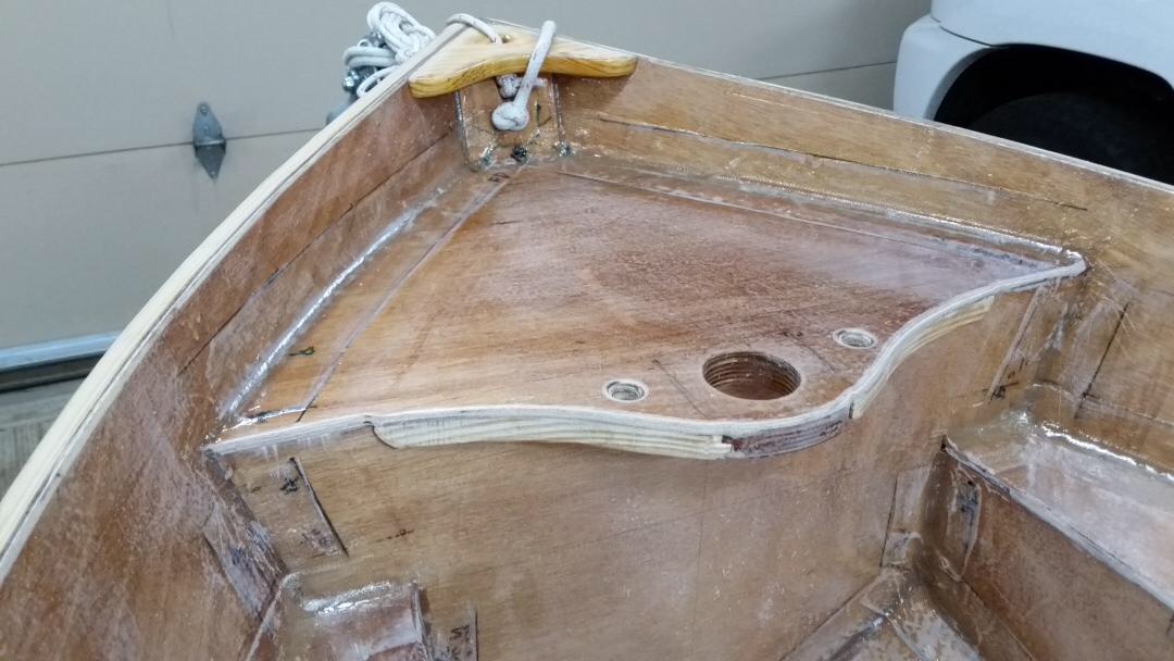
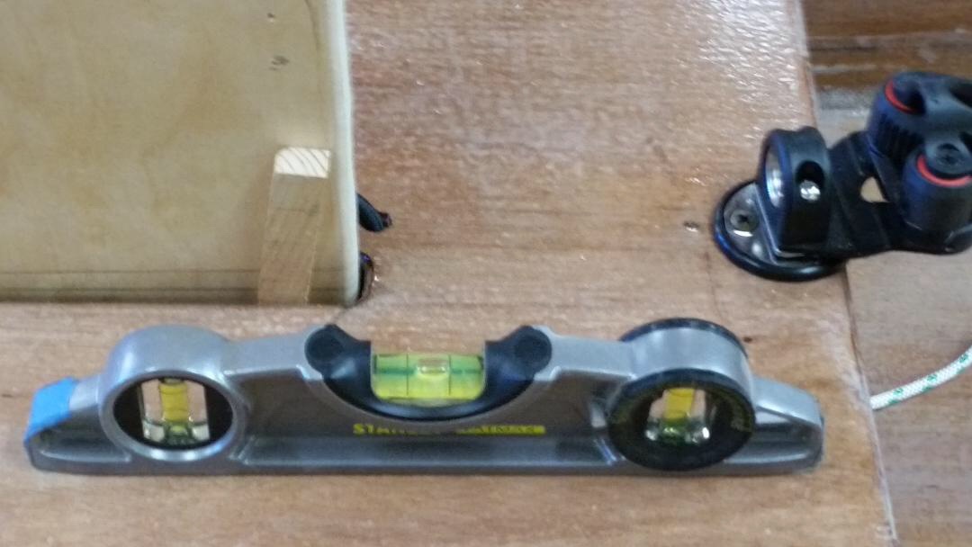
Never like to allow a thin edge of any structure to be exposed ... So I used some leftover yellow pine and made 10 gussets and a “bull nose” to increase all the ten 1/4” edges to 1” and a 1-3/4” bull nose for the leading edge of the CB trunk. Before gluing in place I rounded over the undersides. When dry-fitting I used a Forester bit to drill 5/8” holes thru the 1/4” ply (and just into the) gussets — then used the drill press to complete the holes thru the gussets. Gussets in all the cockpit corners will provide convenient lashing points and substitutes for docking cleats. The 7/8”white oak block on the keel is the base for the mainsheet quick-release cam cleat with a 360 rotating fairlead. The 5/8” holes all are rounded over (5/16” radius, top & bottom). The bull nose. Next will be 3 coats of neat epoxy on exposed wood. Then prepare all surfaces for two coats of primer. May have to wait for warmer weather.


-
Electric Motor for Spindrift 10s . .
Pete McCrary replied to Pete McCrary's topic in B & B Yachts Forum
Wow.!! I had no idea my request for comments and advice would generate such interest. Lots of good information and opinions. Plenty of time to mull it all over before next spring. Anybody want to buy a 2.5 Suzuki w/ 15” shaft? -
Fellow Spindrift builders: Any recommendations for electric motor auxiliary power? Because of the current and tides and fickle wind patterns, sailing on the Potomac River (Leesylvania State Park) without auxiliary power is a safety issue. I've had the unfortunate experience of sailing (from the ramp) UPWIND so that I'd have an easy return, only to have the wind shift 180 just when I wanted to return to the ramp! If I had only oars, I would have been in real trouble. I recently installed hardwood pads on the centerline of Seabiscuit's transom so that my 2.5 Suzuki OBM (29 lbs, 1.5 liter gas tank empty) could be used for non-sailing excursions. The pads do not interfere with full range of motion (ROM) for the rudder. However, after that test, I dry-fitted the pads and OBM off-center to see if I could use the motor for auxiliary power while sailing. Sorry to say, even with the motor mounted right next to either quarter knee (port and/or starboard), the tiller's ROM was significantly limited by the bulk of OBM when the prop-shaft is rotated out of the water. The ROM is only slightly limited when prop-shaft is in the water. Perhaps a much lighter and less bulky electric auxiliary power would work. I'd appreciate recommendations from Spindrift skippers or others that have had experience with electric power for dinghy-sized sailboats.
-
Spindrift 10, #1329 -- "Seabiscuit" . .
Pete McCrary replied to Pete McCrary's topic in B & B Yachts Forum
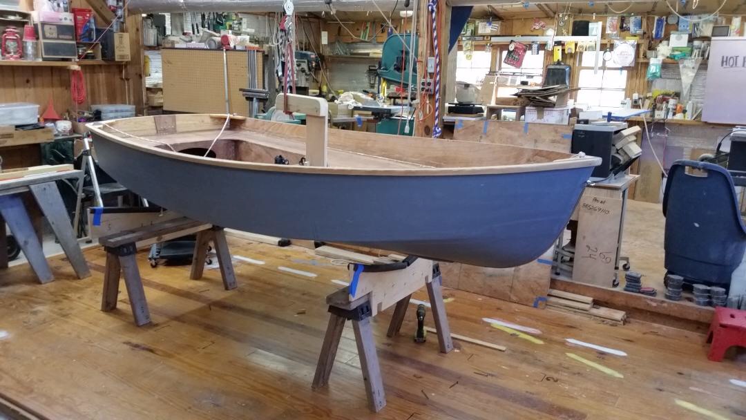
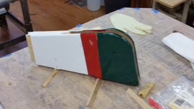
Prep for a half-hour paint job took all morning. Tomorrow the second (and last) coats of green and white go on. Then on Saturday I’ll put her back on her trailer for a sail on Sunday. Might be the last sail of this season. The foredeck will be white. And, initially, the rest of the interior will be Interlux’s Kingston Gray.
-
Spindrift 10, #1329 -- "Seabiscuit" . .
Pete McCrary replied to Pete McCrary's topic in B & B Yachts Forum
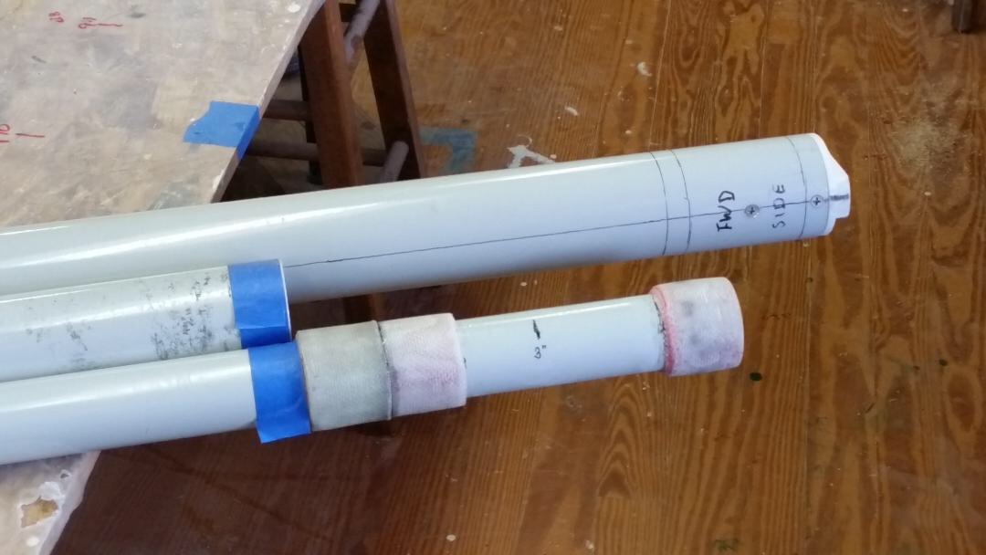
Today the boot got its 2nd (and) final coat of Interlux Brightside paint. Tomorrow I’ll mask the entire boot and apply Sea Green for the bottom and White for the topsides. Note that the color scheme will include the CB and Rudder Assembly. But the rudder itself will be left showing its last coat of neat epoxy. There will be a line painted on the CB so as to show (above its trunk) when the end of the CB is positioned just at the keel. Below are a few pixs showing a nuisance problem when transporting the mast with the tubes nested within each next-bigger tube. Notice that on the mis-sized tube there are smudge marks at a few places along its length. These are caused by the outside of the smaller tube being jostled and rubbed against the inside of the (unfinished aluminum) larger tube. That’s dirty aluminum oxide residue transferred to the nicely finished outside of the smaller tube. There’s only a 3/16” separation of the surfaces. Notice that there aren’t any such smudges on the smallest tube. That’s probably because there’s 3/8” separation of the surfaces — twice that of the other tubes. Here the tubes are assembled for transport. The largest tube is to the right — and the mid-sized tube has been inserted from the left. It doesn’t go all the way in (up to its stop-collar) because it has (within it) the smallest tube — and its stop-collar keeps if from being fully inserted. My solution will be to fabricate 1” FG-tape bushings at each of the two smaller tubes of only 3 or 4 wraps (~ 3/64” thickness, an OD increase of 3/32”) and sand them smooth with tapered edges. They will be a loose fit so as not to impede their “nesting,” but will create a very thin tube a air between the inner and outer surfaces of the nesting tubes. The pixs below show the locations (blue masking tape) of the 4 loose-fitting bushings. The largest diameter tube is at the top. Comments and suggestions are invtied and welcome. It’s an off-season project — so I won’t be doing it right away.


-
Spindrift 10, #1329 -- "Seabiscuit" . .
Pete McCrary replied to Pete McCrary's topic in B & B Yachts Forum
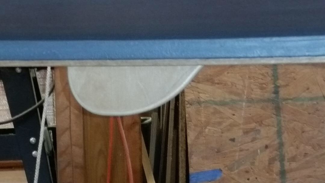
Now I can “flip” Seabiscuit as well as lifting her. Here are the photos: Level side-to-side. Note wedge forcing lift-vector to starboard a little. Pretty close to level fore-to-aft. Under, looking to starboard. Looking to port. Hanging by a thread(s?). C.G. about 5” aft of CB Trunk. A loop thru a pulley. Ready to be flipped, starboard down. I rotated her about 45 degrees (1/4 of a half-roll) with ease — but stopped there because the cradles weren’t yet rigged for a top-down boat. Now I’ll drop her top-side-up and mark the waterline. Then flip her for masking and painting the boot (red). Haven’t decided whether to leave the bottom with just the AwlGrip 545 primer— or use the Interlux Sea Green that I have. It won’t be any anti-fouling paint. Hope to get in one more sailing day this year. Looking for a warm day!


-
Spindrift 10, #1329 -- "Seabiscuit" . .
Pete McCrary replied to Pete McCrary's topic in B & B Yachts Forum
The lifting hook’s final dimensions were adjusted so that it could be fabricated from the temporary bulkhead. Later, I’ll post its actual dimensions. It worked as expected. The C.G. of the boat (sans rudder assembly and all rigging) determined to be approximately 3.5” aft of the aft edge of the CB Trunk — weight at 110 lbs. That’s about 20 lbs higher than the weighing made at the “turnover.” Difference would be the addition of the keel/skeg, worm shoe, and half oval at the stem; three coats of neat epoxy; two coats of primer on outside (below gunwales); filleting and fiberglass taping of interior and seat tops; breast hook & quarter knees; and hardware. Note that the 2 x 4 on the lift-bar is not for strength, but rather to move the lift-vector inboard by 3/4” — which brings it very close to the geometric bow-to-stern centerline. Next, I’ll post photos of the boat lifted. And (if all goes well) I’ll reveal another innovation using the lifting rig.

-
Spindrift 10, #1329 -- "Seabiscuit" . .
Pete McCrary replied to Pete McCrary's topic in B & B Yachts Forum
But wouldn’t you have go under the boat to insert the dowel after dropping the “hook” into the CB trunk? And the lifting force on the dowel would all be on the side next to the keel batten. Or, have I miss interpreted your suggestion? -
Spindrift 10, #1329 -- "Seabiscuit" . .
Pete McCrary replied to Pete McCrary's topic in B & B Yachts Forum
Thank you Brian for the comments on sailing Seabiscuit and the numerous suggestions you made at the Messabout. Especially furling her sail with battens in place. You helped make the “shakedown” cruise very informative. I now have a pretty good punch list for Seabiscuit projects over the off-season. -
Spindrift 10, #1329 -- "Seabiscuit" . .
Pete McCrary replied to Pete McCrary's topic in B & B Yachts Forum
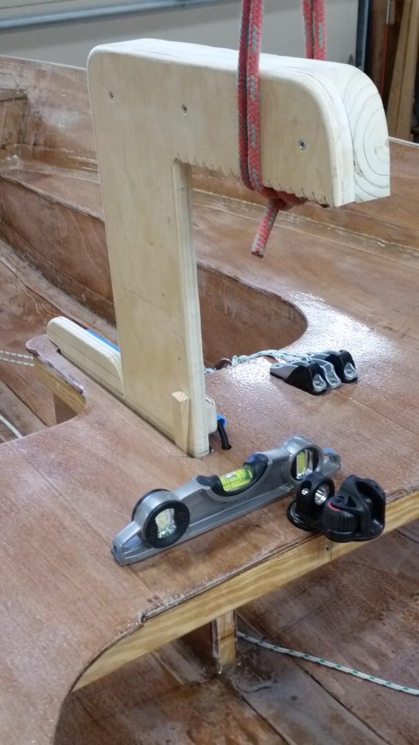
Thanks, Don. For colors, I’m thinking of white topsides and foredeck; light gray interior; sea green bottom; red WL boot; mahogany stain on pine gunwale, boom, and tiller. The topside, boot, and bottom colors to extend to the rudder assembly. Might leave the bottom as-is, with just the gray 545 primer. But I do have the green Interlux. One convenience of a small boat is that much can be done without the help of friends, neighbors, family, etc. — such as lifting off trailer onto her cradle. To this end I’m putting to good use the temporary-3/4 ply bulkhead that came with the B & B kit. It will look like this: I have already used a x3 pulley rig to lift Seabiscuit — but [to attach the pulley] I just looped a line under the midship thwart. Although the weight is only about a hundred pounds, I worried that the thwart could pull away from the top of the CB housing [it’s just glued on, no FG tape or fillets]. Also, since the attachment was about 6” below the gunwales, when lifted, the boat tended to tilt sideways. With this longer lifting “hook,” she should hang quite level and steady.
-
Spindrift 10, #1329 -- "Seabiscuit" . .
Pete McCrary replied to Pete McCrary's topic in B & B Yachts Forum
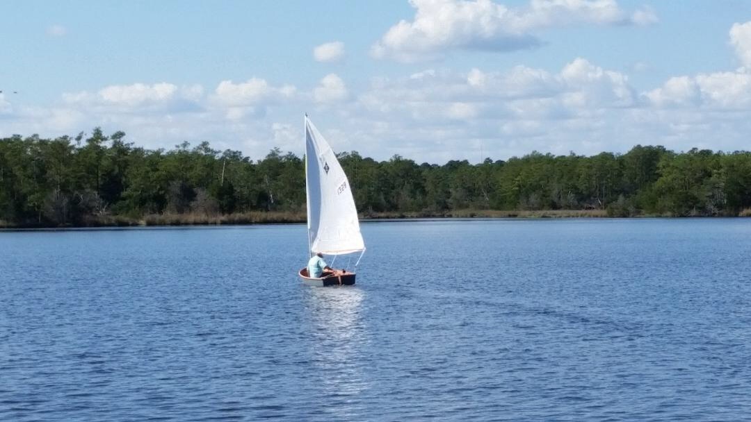
We certainly enjoyed this year’s Messabout and Seabiscuit’s maiden shakedown cruises. All went well with generation of a modest “punch list.” At 7am Sunday we hooked up Seabiscuit and had breakfast at Charlie’s Restaurant. By the time we finished, the rain started — and continued (sometimes heavy) all the way the 325 miles to Manassas, Virginia. Home safe by 2pm. Using Seabiscuit as a prop, Graham demonstrates a “running” technique. Ready for launch. In the water waiting for her skipper. Saturday, Brian put her thru her paces. Next will be a complete paint job. Also the mast will be lengthened by about 3/4” and the trailer’s bow-roller support strengthened.