Pete McCrary
-
Posts
692 -
Joined
-
Last visited
-
Days Won
40
Content Type
Profiles
Forums
Events
Everything posted by Pete McCrary
-

Core Sound 20 Mk 3 -- #4 "Chessie" . .
Pete McCrary replied to Pete McCrary's topic in B & B Yachts Forum
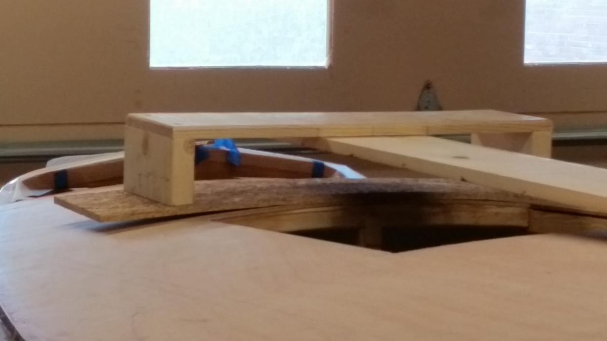
Here's one that should be a warning to new builders. This gave me a big scare !! At the start, while building the CB trunk, I kept a 2 x 4 x about 36" (measured thickness 1.5") in the slot. Nevertheless, after cutting the slot it was obvious that the width was not a constant 1.5" !! Here's the profile going aft every 8" : 1"+ 17/32 @ the fwd end 1+9/16 1+7/16 1+5/16 1+9/32 1+5/16 1+7/16 @ the aft end It's 3/16 shy of 1.5" (at the center). That scared me! I first noticed the problem when routing-out with the trim bit: the sides of the left-over center cut-out were not parallel. If I were to build another -- I would have temporary spacers in place for the insertion of the module (to be removed after the cut-out). So, I dry-fitted the CB. She slips right in with about a 1/16" to spare (i.e., 1/32" each side) !! That's good news. I wish I had a had a little more leeway (in the slot) just in case the CB (or CB well-sides) might "swell" a little. Graham thinks it'll be OK without trimming the CB. He mentioned that the manual recommended that temporary spacers be added before insertion of the module -- but I missed that. However after having built 8 boats (4 with CB trunks), I shouldn't have needed a warning. As an after thought here is my concept for the temporary spacer: Next I'll finish the trimming required for the Bailers, roundingover the CB slot, and their final edge treatment with epoxy and glassing. PS -- Robert, I like "Puff" as a name for "Chessie's" mascot !!

-
Core Sound 20 Mk 3 -- #4 "Chessie" . .
Pete McCrary replied to Pete McCrary's topic in B & B Yachts Forum
Yes, two Anderson Bailers. Graham assures me that the head created by 3 knots [forward] will "easily" fill the ballest tank to overflowing -- even though the footwell sole is above the waterline. That's a lot better than topping off by reverse bailing! Here is a photo of the repair. . Good as new !! This mishap could'v been much worse than just the loss of a day's progress.
-
Core Sound 20 Mk 3 -- #4 "Chessie" . .
Pete McCrary replied to Pete McCrary's topic in B & B Yachts Forum
I thought maybe that I'd skip posting this DUMB mistake on the forum. But a fellow builder may benefit from the lessons learned. At least the "tuition" for the lesson wasn't to expensive. Here's the mistake: . I blamed it on poor lighting. And insufficient guidelines. . The plan -- using the "cutout" material already glassed, both sides. . The fix. Of course, both inside & outside will be smoothed over. . The tuition. A lost day of progress! Tomorrow's progress is already lost to continuing "health" appointments. But Wednesday we're expecting cooler weather.


-
Core Sound 20 Mk 3 -- #4 "Chessie" . .
Pete McCrary replied to Pete McCrary's topic in B & B Yachts Forum
Keel batten and prep for cockpit seat backs (coamings) ... Sixteen little ducks (dowels) in a row ... At this point only the inside surfaces are to be epoxied (just one coat using Peel Ply release fabric). If it's not too hot, I'll lay on the epoxy this afternoon.

-
Core Sound 20 Mk 3 -- #4 "Chessie" . .
Pete McCrary replied to Pete McCrary's topic in B & B Yachts Forum
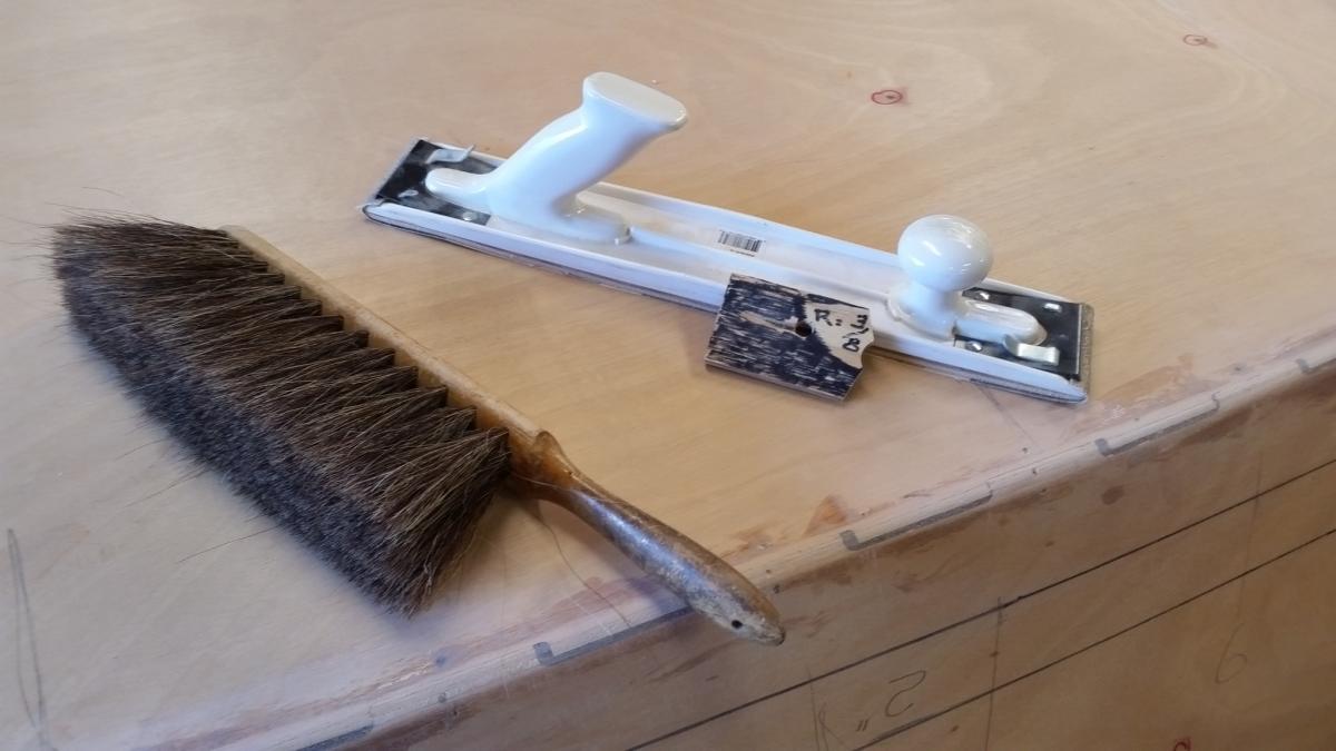
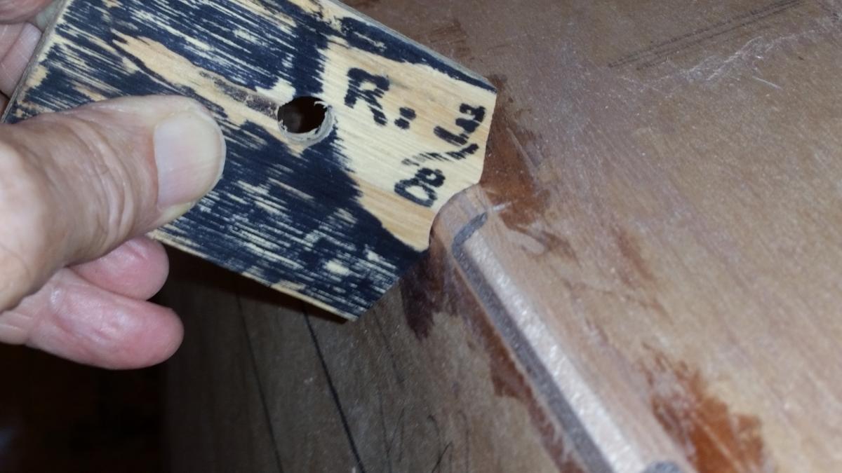
A little more progress ... Dry fitting the keel batten (anyone know the proper nauticle name?) and the SS half-ovals: I wanted a graceful transition from the 1/2" ho to the 3/4" one. So I made a yellow pine wedge that straddles the 1/2" ho and would also be a support for the 3/4" one. They overlap one another the spread of a pair of screw-holes. The wedge won't be glued in place, but held firm by the convex top of the 1/2" ho and the concave underside of the 3/4". Of course all will be well bedded. The forward end of the 3/4" ho will be filed down so as not to snag on roots, gravel, sand, etc when being beached. The edges modified between bottom planks and the transom: In order to form a sharp trailing edge to the boat's bottom, I framed a trough at the 1/4" radius along the edges formed by the transom and bottom planks. The photos show the results. Any imperfections will be smoothed over with epoxy putty before applying the epoxy primer AWLGRIP 545. Glueing on the 15' keel batten: The aft end of the 1/2" SS ho tucks under the keel batten. So that it (the 1/2" ho) can be removed (for installation and bedding after painting) its aft 1/2" has been coated with paste floor wax. The dry-wall screws will be .removed tomorrow and be replaced with 3/16" dowels in each hole. The dry-wall screws only need a 5/32" hole -- but 3/16" was the smallest dowel that I could find. So, the batten has slightly oversize holes. The squeeze out was made into a small fillet on each side of the keel batten. Except for the tapered first 3', the batten is 7/8" wide and 3/4" high. It will be very strong and resist any side-loading that it may encounter. Next, I'll rout out the CB slot and the openings for the Anderson Bailers.


-
Core Sound 20 Mk 3 -- #4 "Chessie" . .
Pete McCrary replied to Pete McCrary's topic in B & B Yachts Forum
Paul,... How would you manage to cut cleanly thru the two overlapping fabrics and not nick the fiberglass? -
Core Sound 20 Mk 3 -- #4 "Chessie" . .
Pete McCrary replied to Pete McCrary's topic in B & B Yachts Forum
Drew -- I overlapped them ~ 1/2". I marked the keel every 24" and cut panels to 25". When I mark the edges when "dry-fitting," -- the trailing edge mark is on the previous panel, and the leading edge mark is on the glass. Before dry-fitting the next panel, I tape the top edge of the [just-fitted] panel to the other side of the bottom. After all panels are in place and marked on top and both sides, I then (starting at the stem) flip each panel over to the side not being glassed (their bottom sides up). Then (starting at the transom) I wet the area that is already marked to be under the first panel (plus about an inch). With the epoxy mix that remains, I wet the top edge of the next area. Then, back to the first area, I flip the Peel Ply over onto the wetted glass. When I've smoothed out about half the PPly, I tell the helper to mix the next batch -- indicating the number of squirt-pairs, depending on how much was left over from the first batch. Because the beam is so wide, I usually need the helper (on the other side) to hand-over to me the PPly panel that I'm laying on the wetted section. Recall that the top edge is already fixed in place (with masking tape). It's pretty easy to just lay it down. I've learned that it can be moved easily and wrinkles removed with the palm of your hands. The squeegee needed for the final adjustments. The edge of the overlapped panel leaves a small ridge which is easily removed with a scraper. Much easier to fix than a spot where adjoining panels don't quite meet. Hope this helps. -
Core Sound 20 Mk 3 -- #4 "Chessie" . .
Pete McCrary replied to Pete McCrary's topic in B & B Yachts Forum
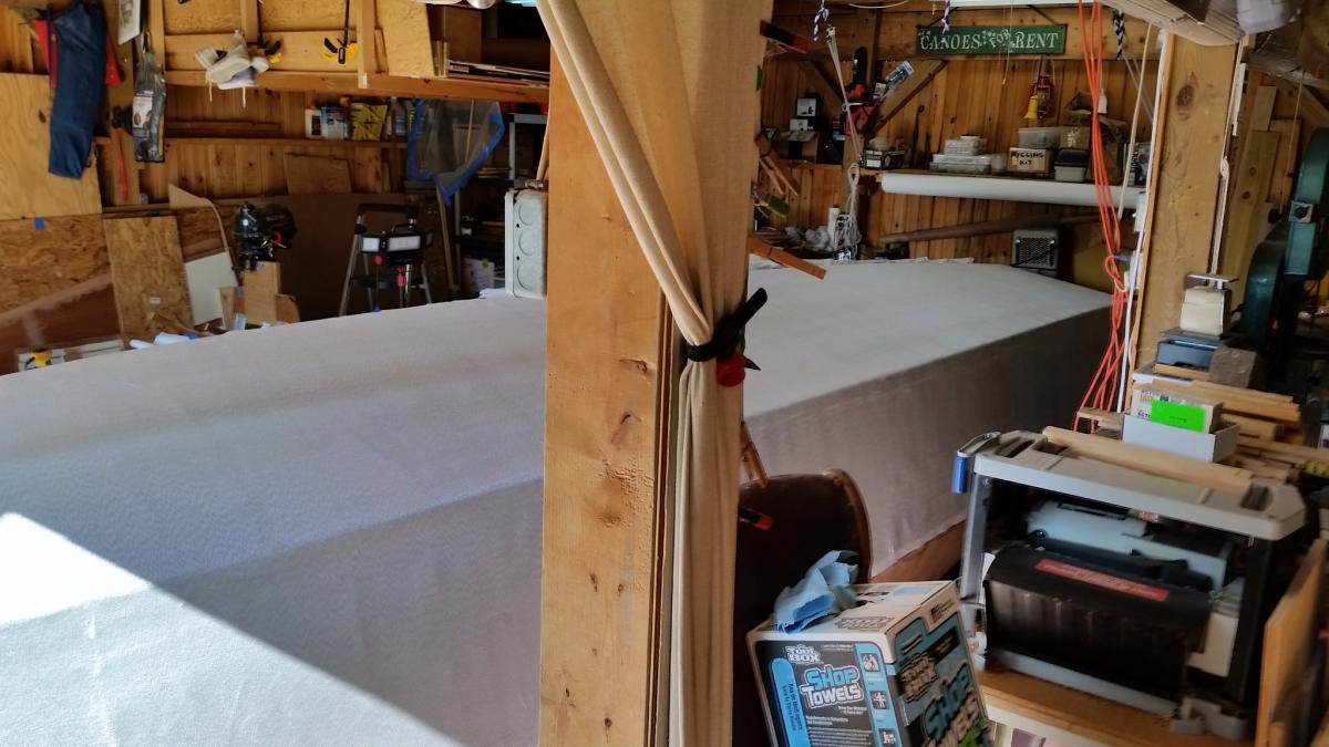
Paul356,... Here's the report I sent to Alan: "The port-side glassing w/Peel Ply was much easier -- but the results are about the same. What made it easier was that I actually laid out each PPly panel over the glass as a "dry fitting" and marked (felt pen) its location (top and both sides) right on the FG. Then the same with the next panel marking its location (top and leading edge on the FG and trailing edge on the previous panel of PPly). Each panel was numbered and placed on the side [not being glassed) and its top edge taped to the other side -- so that I only needed to flip it over to the side just wetted. I applied epoxy only for the first panel. That required 10 pairs of squirts (a little left over for the leading edge). That way the epoxy was fresh for each panel. As we moved forward, the epoxy batch was reduced with the last one only 6 pairs of squirts. The process was much easier and took about 20% less time. It was also easier to squeegee the PPly panels down onto the FG. "However, although we had a better quality product, it still had a significant number of flaws. Maybe it's quite good -- I just don't have anything to judge it by. I'm going to follow [Alan's] suggestion [to fix the flaws] by applying the Interlux Watertite Epoxy Filler on the obvious flaws and then two coats of the AWLGRIP 545. I think it will be a very nice end product." If I made another boat, I'd use the Peel Ply again. The second application was definitely easier although we only saved about 20% of our time. The prep for each day took a full work day (i.e., for me ~ 4 hrs). I couldn't do it [the application] myself -- full-time help was essential. To make removing the Peel Ply (after an overnight cure) easier, be sure to leave a dry edge for each panel. And don't wait for a 2nd day of curing. Also the PPly can be removed by "ripping" off small (3 to 6 inch strips) rather than entire panels. With a helper, Graham glassed both sides of the bottom of his CS17.3 in one day! But, of course, he's an experienced professional. -
Core Sound 20 Mk 3 -- #4 "Chessie" . .
Pete McCrary replied to Pete McCrary's topic in B & B Yachts Forum
Thanks guys. Relieves a lot of uncertainty. For my PocketShip I had flexable bunks with "shock absorbing" qualities. Instead of the 2 x 4s or 6s that came with the trailer, I fabricated bunks from pairs of 1 x 4s. Screwed together at the middle -- and at each end with carriage bolts (heads countersunk) tightly thru the top plank and "loosely" thru a slot in the bottom plank. Before assembly, the inter surfaces of each plank was waxed. They were plenty strong for their purpose and very flexable. Mine had carpet on the top plank -- but this time, like Dave, I'll use the pvc. And his idea for the longitudinal plank between the rollers is a good one. It would also prevent a big problem if you tried to launch with the CB already down! I've always put "running boards" on my trailers. Right up to the hitch. I could usually launch without wadeing into the water. It's also a good platform for working the crank. -
Core Sound 20 Mk 3 -- #4 "Chessie" . .
Pete McCrary replied to Pete McCrary's topic in B & B Yachts Forum
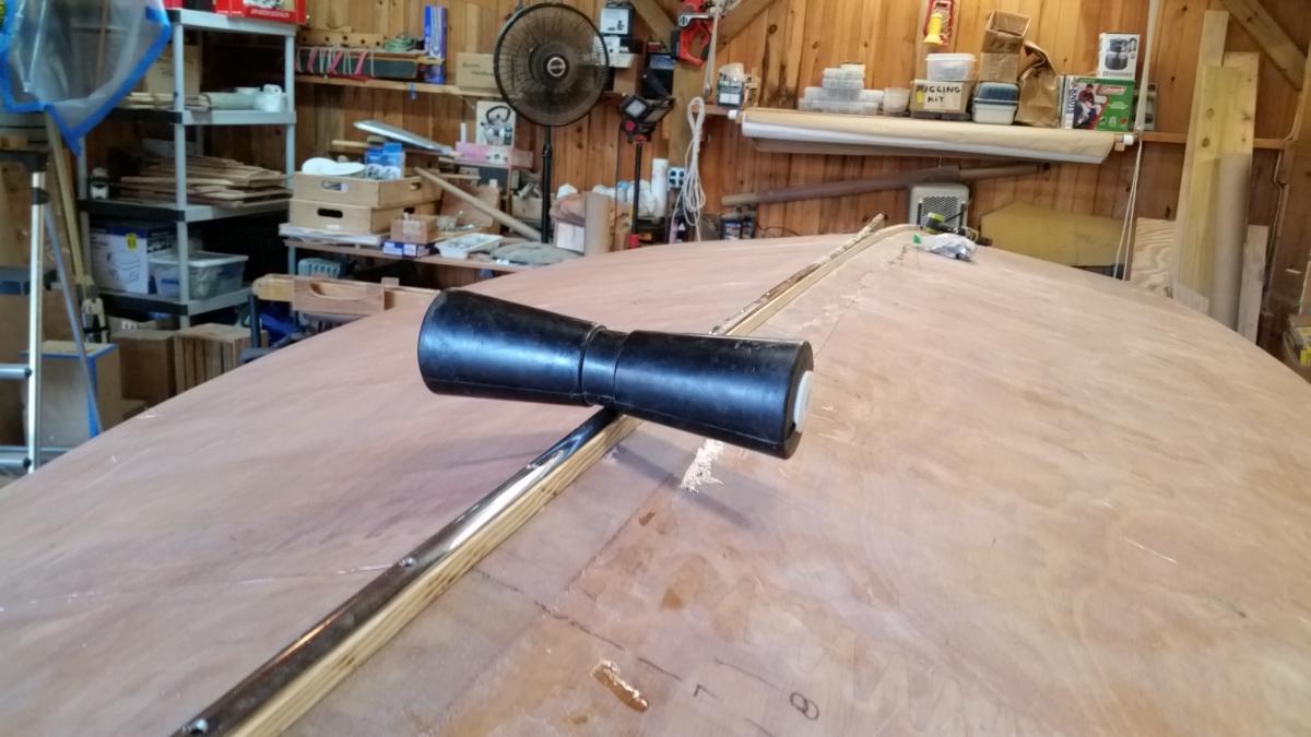
As I'm installing the keel "batten" and 3/4" half-oval, it occurred to me to "dry-fit" one of the trailer's (two or three) rollers. Here's a photo of it. With the trailer setup that I will have, it appears that almost the entire weight of the boat (and equipment) will rest on the rollers. Of course, there will be side "bunks" to keep the boat upright, but the weight they support is practically nil. And the trailer frame is suspended with shock absorbing leaf springs rated for about 2,000 lbs (i.e., ~ 1,000 each). That's 2,000 for trailer frame and boat. QUESTION 1: Is the boat designed such that all its weight may be supported on its trailer at (as few as) two points on the keel batten (xsection: 7/8" x 3/4")? QUESTION 2: If that isn't advisable, should I be looking for a different trailer configuration? QUESTION 3: What trailer / roller configurations have other builders utilized with success? Note: I have a third roller that could be placed approximately under Blk 2. But distributing the weight equally would be problematic. Thanks in advance for comments and suggestions.
-
Core Sound 20 Mk 3 -- #4 "Chessie" . .
Pete McCrary replied to Pete McCrary's topic in B & B Yachts Forum
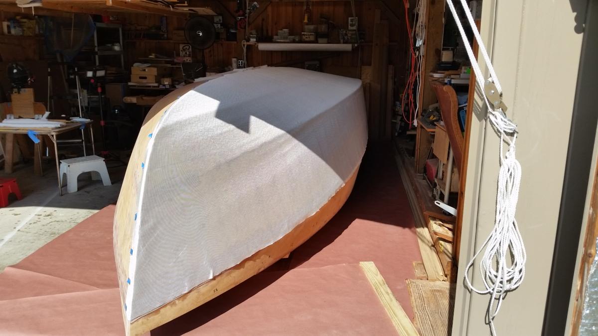
"Chessie's" starboard side of her bottom now is covered with fiberglass. We (Annie and I) started at 9:20 am and finished at 1:30 pm. Four hrs 10 minutes. Temp ~ 70 at start and ~ 78 at finish. Hard tedious work. But we are still friends. The epoxy was setting up faster [at the end] than I could (easily) keep up in laying down the Peel Ply. But I think it will end up a nice job. Tomorrow will tell. . We wil be a little faster when doing the port side. The Peel Ply comes off tomorrow. And then I'll trim and sand the centerline and dry-fit the fiberglass on the port side. We'll do the second half Sunday morning. But we'll start at 8:30 am instead of 9:30. Hopefully, that will be the last of fiberglassing!
-
Core Sound 20 Mk 3 -- #4 "Chessie" . .
Pete McCrary replied to Pete McCrary's topic in B & B Yachts Forum
My guess is probably not. Alan and Graham do this on their Core Sound boats. -
Core Sound 20 Mk 3 -- #4 "Chessie" . .
Pete McCrary replied to Pete McCrary's topic in B & B Yachts Forum
It's 10 oz. Recommended by B & B. -
Core Sound 20 Mk 3 -- #4 "Chessie" . .
Pete McCrary replied to Pete McCrary's topic in B & B Yachts Forum
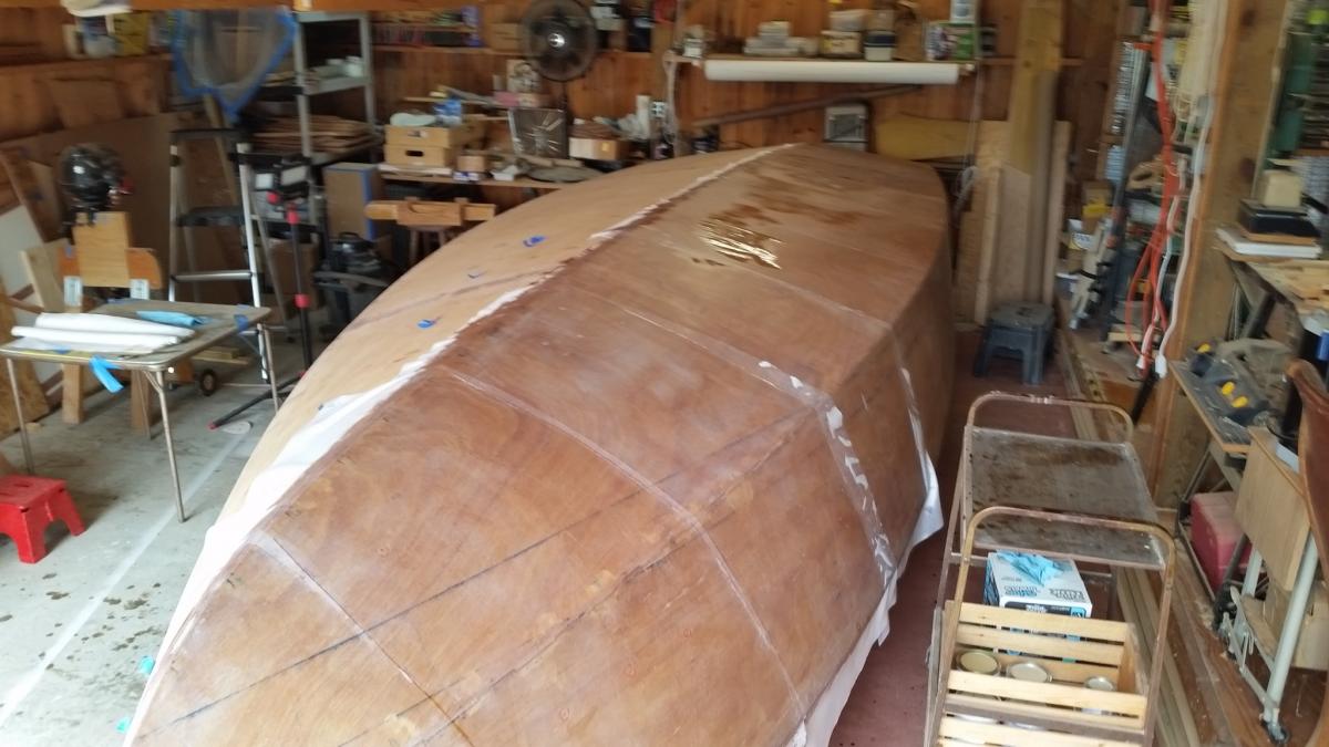
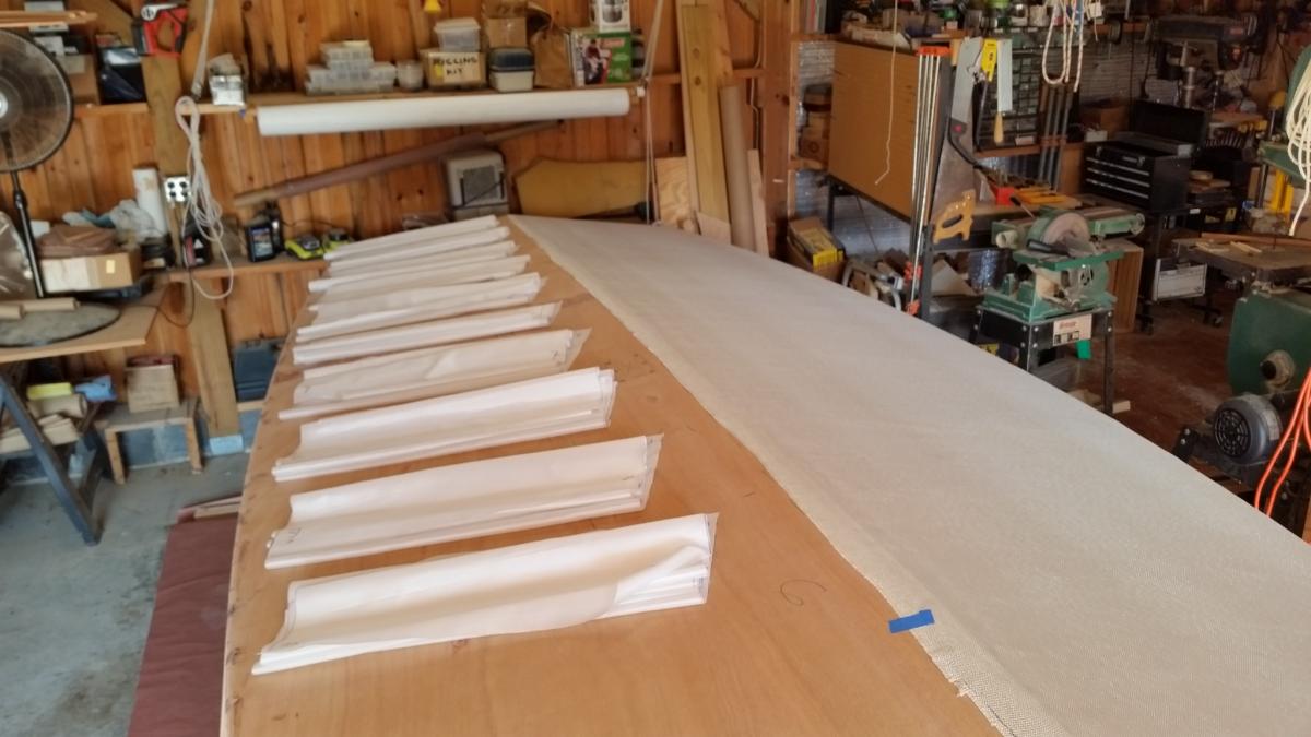
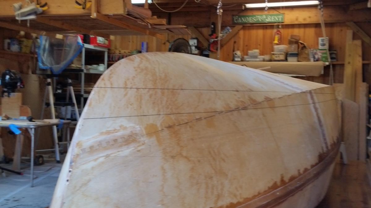
Now she's ready for glassing the starboard side of the hull -- tomorrow. I'm using "Peel Ply" so I expect not to have to "fill-the-weave" and a 3rd coat. Annie is my helper and mixer. We'll get an early start and hope to be finished before noon. Forecast temps 70 to 80. The second photo shows ten 25" Peel Ply panels pre-cut to cover 24" sections as I wet the fiberglass from stern to stem. We'll remove the Peel Ply the next morning. On Saturday we'll prep for a Sunday glassing of the port side. Cool weather also expected. . A view from the shop.


-
Core Sound 20 Mk 3 -- #4 "Chessie" . .
Pete McCrary replied to Pete McCrary's topic in B & B Yachts Forum
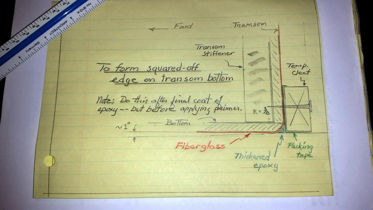
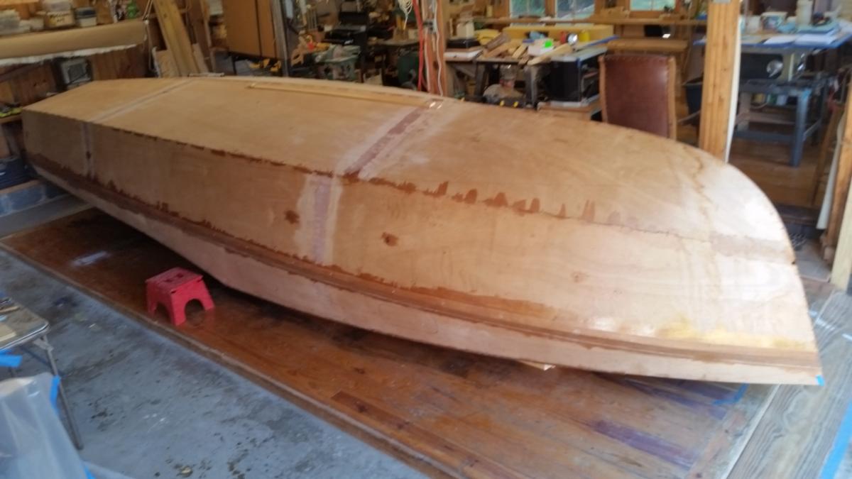
Getting ready for glassing the bottom & side panels. For a "planeing" boat, performance is improved if the bottom / transom edge is square (or even at an acute angle). Alan pointed this out. But the transom / bottom edge should be rounded over so that fiberglass can reinforce the joint by wrapping it over the edge. That requires ~ a 3/8" radius. To get the square edge, here is what I plan: Of course, the dry-wall screw-holes should be filled in after cleat removal. Today, I finish sanding and some thickened epoxy filling a few dinks, holes, etc. Tomorrow I'll sand over the touch up spots, then Annie will help me layout the fiberglass on the starboard half of the hull. And I will pre-cut about A dozen 24" panels of Peel Ply. Hopefully, all will be completely ready for application of FG & Peel Ply on Friday am. Temperatures predicted in the 70s. If all goes well, then on Saturday I'll prep the port-half for fiberglassing it on Sunday. Then on Monday: priming, painting, etc. !!!!!!!! GETTING CLOSER.


-
Core Sound 20 Mk 3 -- #4 "Chessie" . .
Pete McCrary replied to Pete McCrary's topic in B & B Yachts Forum
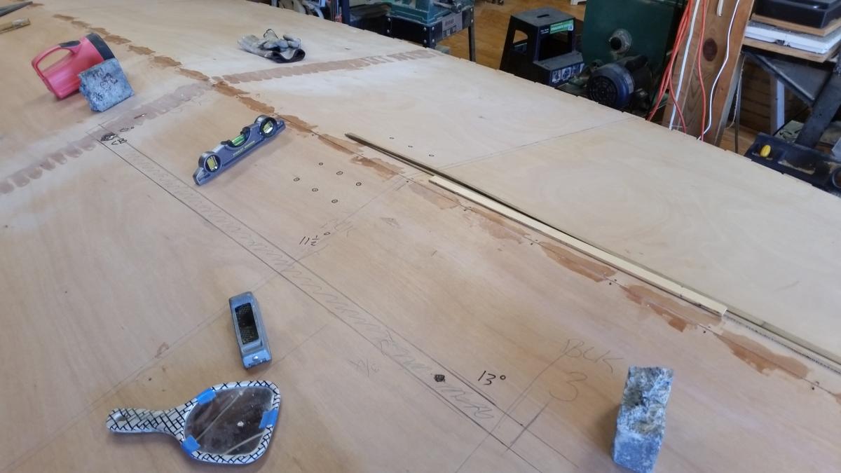
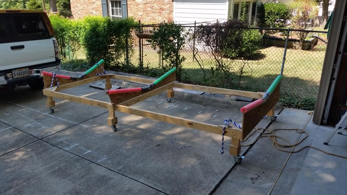
Just before the rollover I remembered to mark the locations of the two Anderson Bailers. Much easier to do before than after. And the first thing (after the rollover) was to permanently mark the water line boot. The marking will show thru the fiberglass and epoxy. I also carefully located the CB slot and measured the angle that will be set into the router base when routing out the slot (with a flush trim bit). After the rollover, my son Jim suggested that I should pad the cradle for gentle treatment of the bottom after "Chessie" is once again upright. He said "swim-noodles" would do the job. So, I got 6 of them. They are available only seasonally -- Wallmart was out, but Target had them in red and green. Tomorrow I'll start working on making the keel and chines ready for glassing.


-
Core Sound 20 Mk 3 -- #4 "Chessie" . .
Pete McCrary replied to Pete McCrary's topic in B & B Yachts Forum
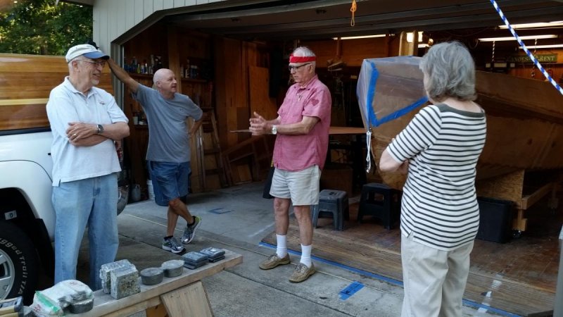
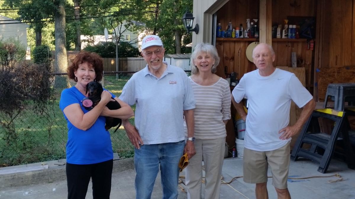
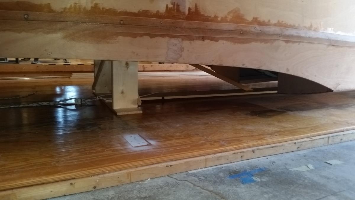
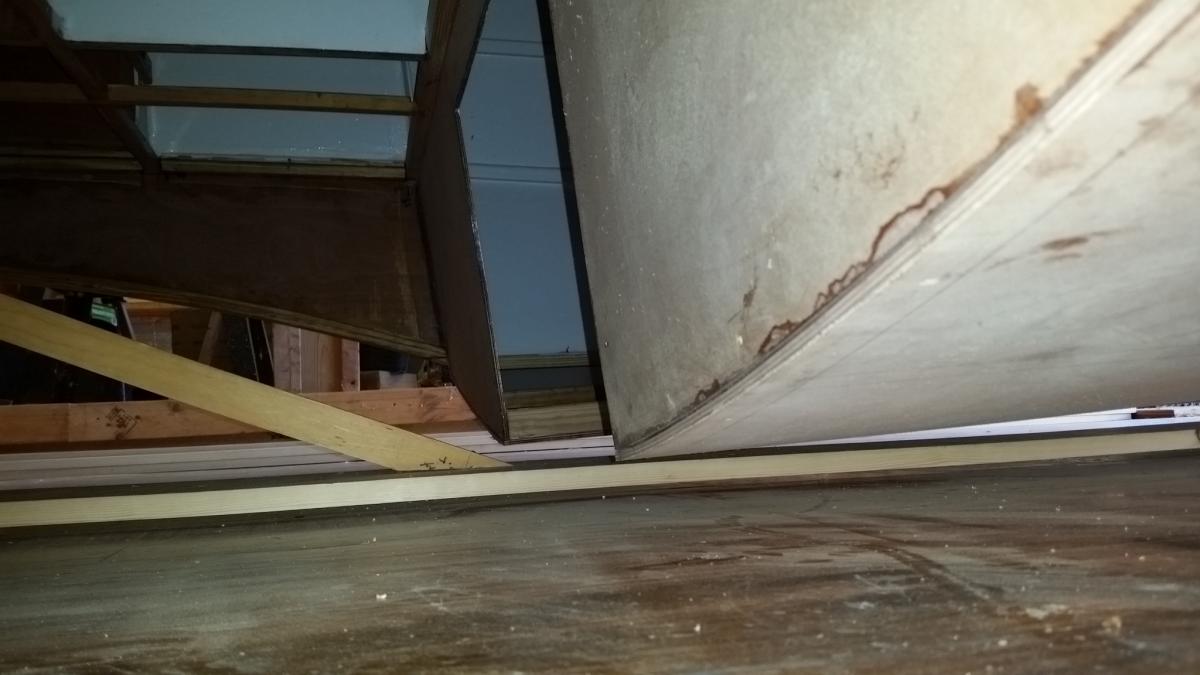
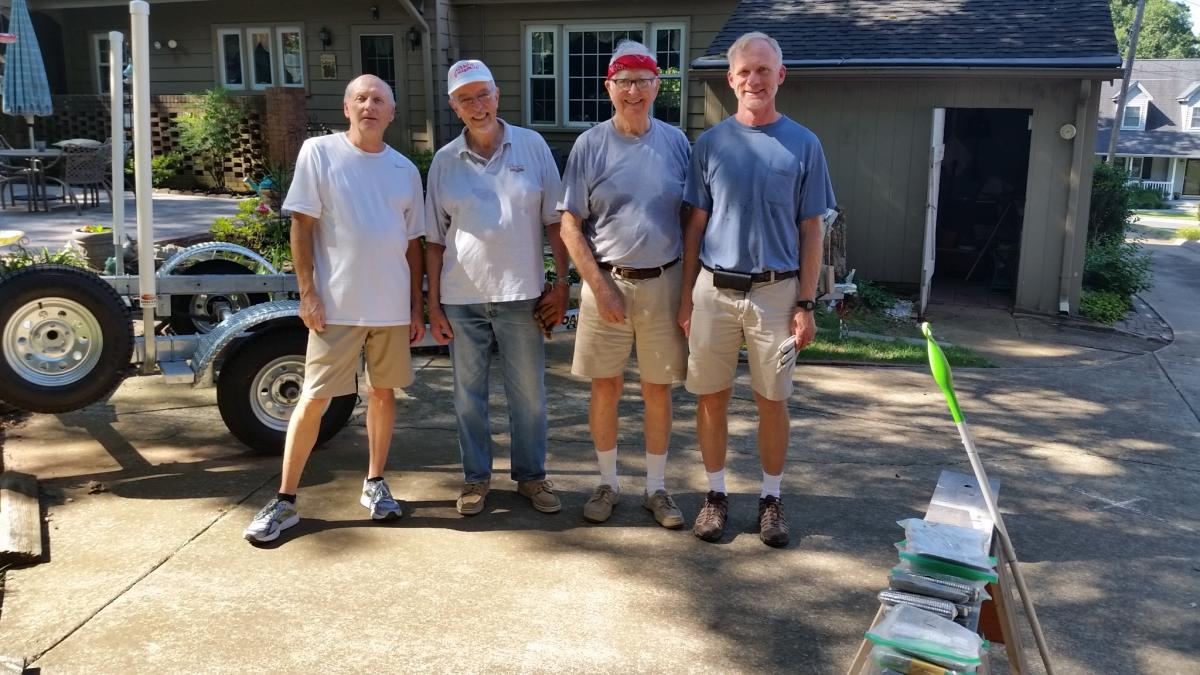
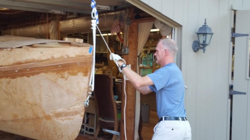
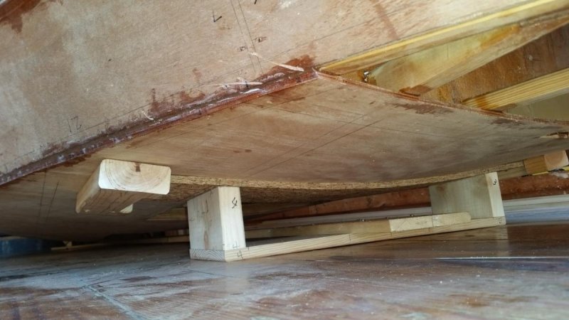
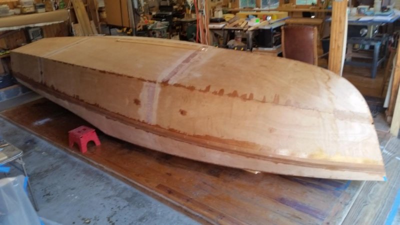
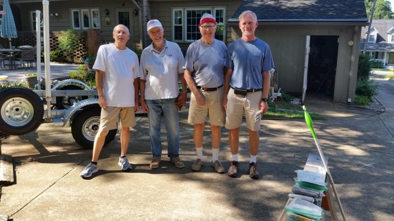
"Chessie's" rollover crew assembled at about 9:30 am, Saturday, August 27. Here they are: Some of the crew: Brenda Wine, Henry Felber, Annie McCrary, Dale Wine. Jim at the bow, Dale and Henry at the transom. She's part-way over. Above: forward pedestal, aft pedestal, mid-ship floor clearance, & ready for glassing prep. The floor surface and pedestal bases were waxed before the rollover. She slides ok on the floor with a heafty push. No back strains. Dale, Henry, Pete, and Jim. We were finished by about 10:30. All went well.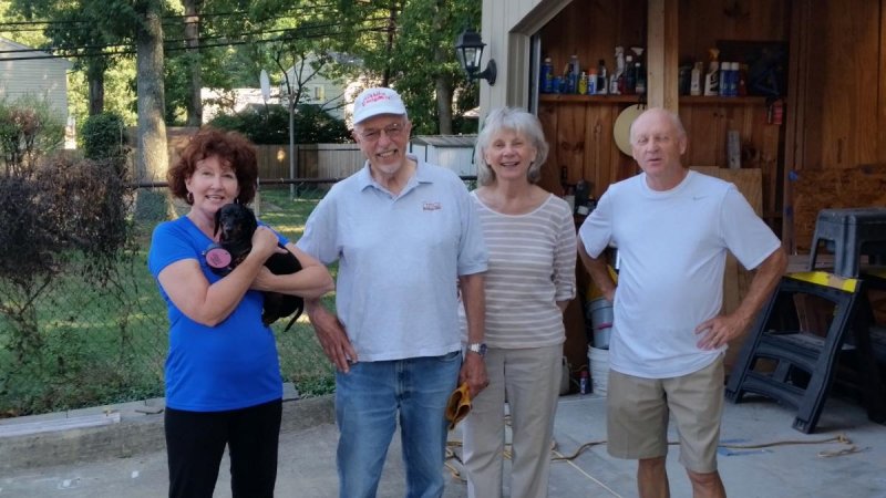


-
Core Sound 20 Mk 3 -- #4 "Chessie" . .
Pete McCrary replied to Pete McCrary's topic in B & B Yachts Forum
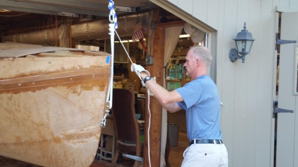
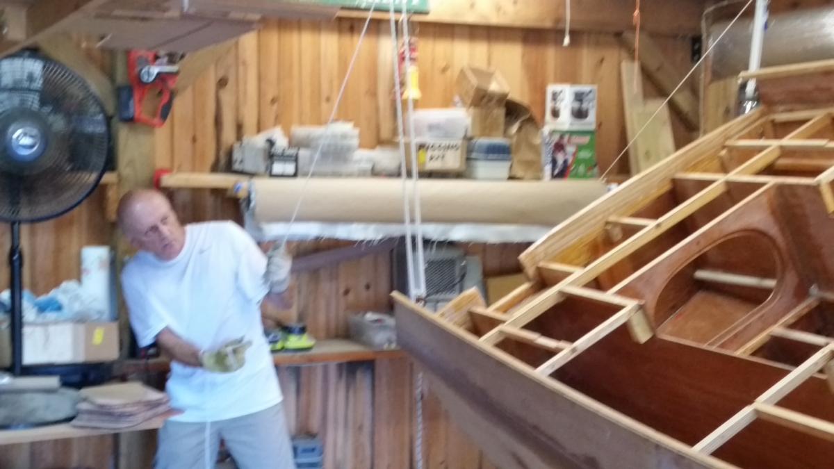
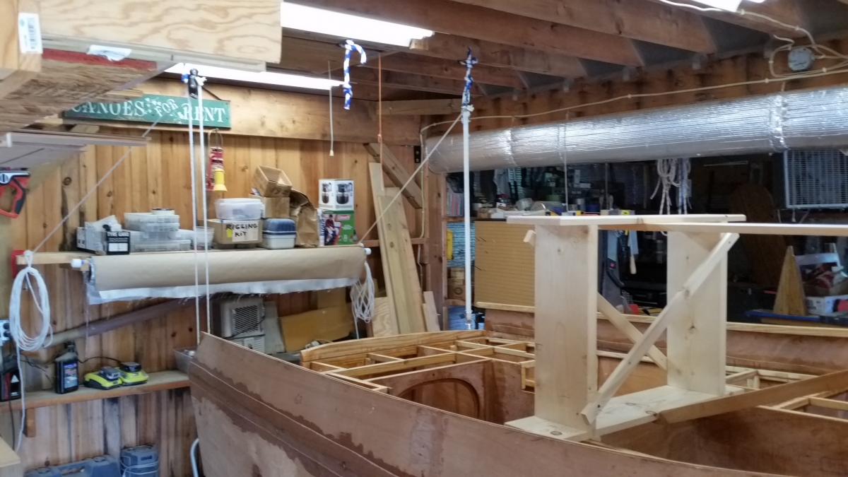
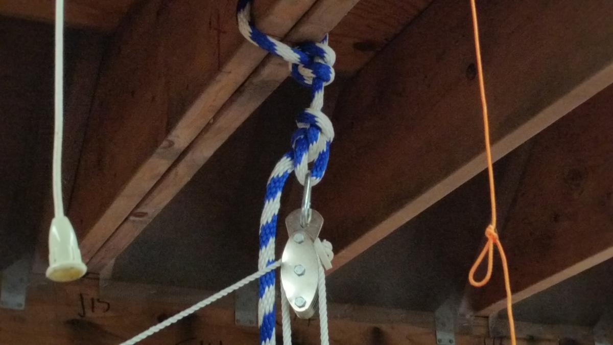
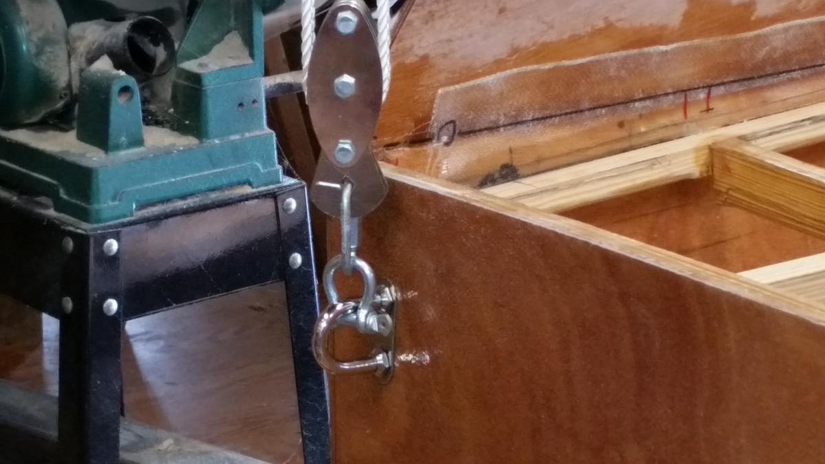
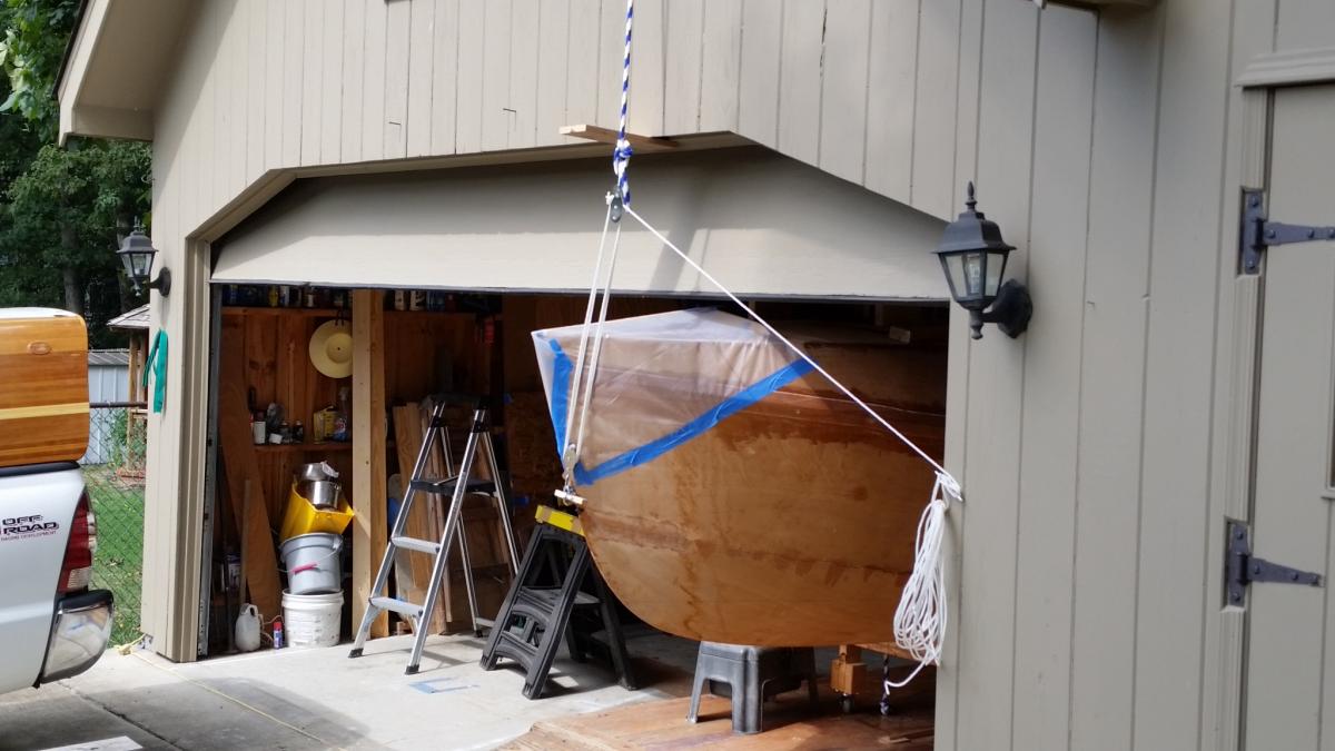
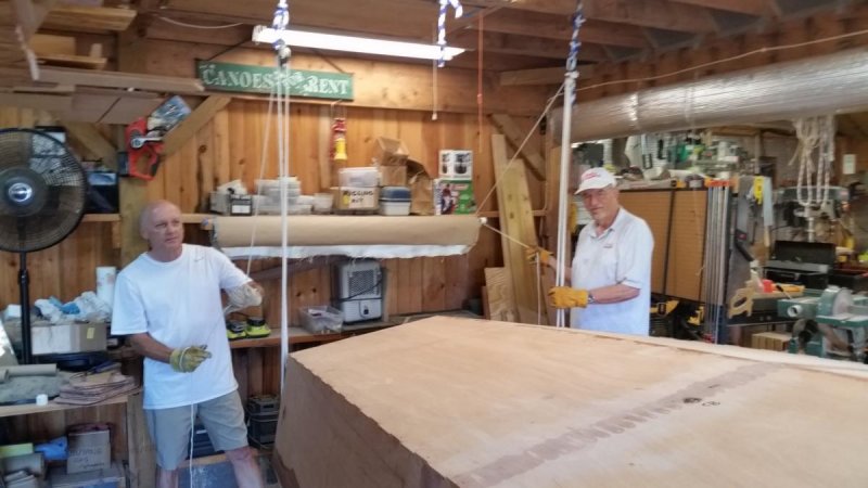
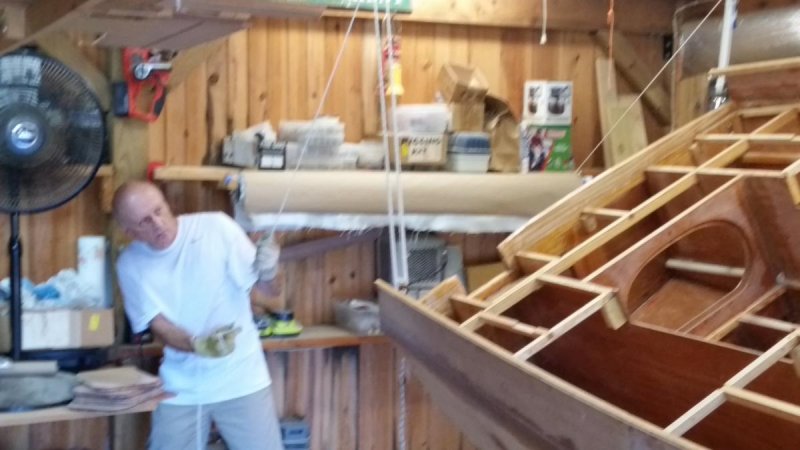
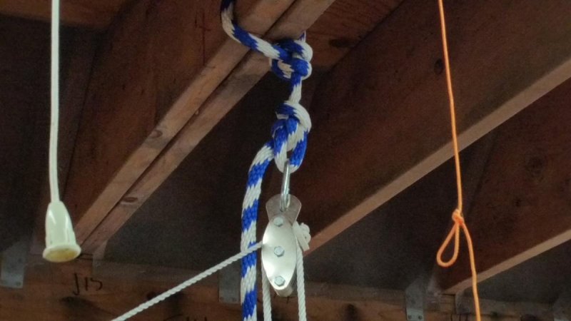
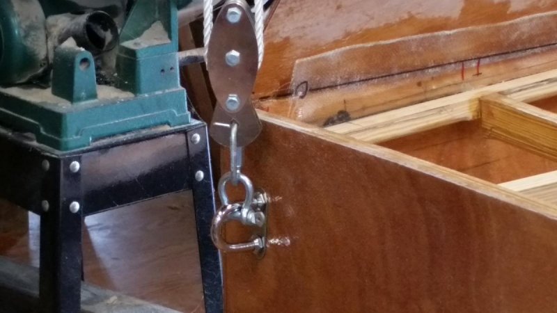
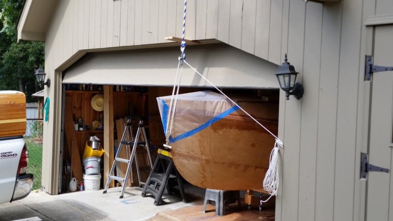
Getting ready for the rollover set for Saturday morning. I know many old timers say it's not such a big deal -- but to me it is. I don't want any mishaps. I'm going with the three pulley system mainly because with it I can manage a transfer to/from the trailer by my self. Same for setting her on her cradle for off-season maintenance or repairs. Here are pixs of the setup: My rollover crew will be my oldest son, Jim, and helpful neighbors. Jim is to become a grandfather in February. His first son, Joe McCrary, is a second year resident physician in Portland, Maine. He and his wife, Dove, are expecting our 6th GREATgrandchild in February. Forgive me for excessive pride ... . Doctor Joseph McCrary, at home, ready for duty.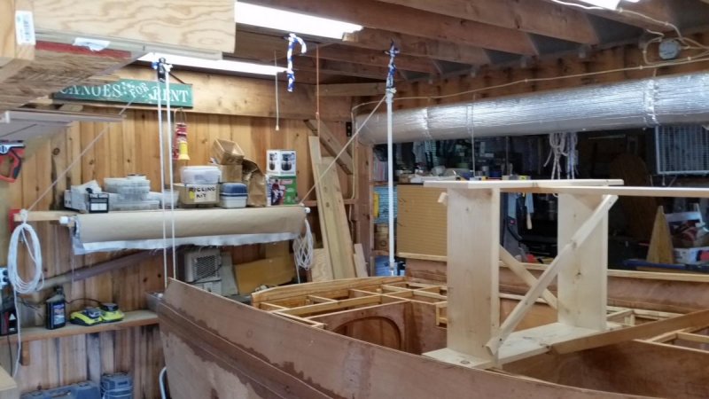

-
Core Sound 20 Mk 3 -- #4 "Chessie" . .
Pete McCrary replied to Pete McCrary's topic in B & B Yachts Forum
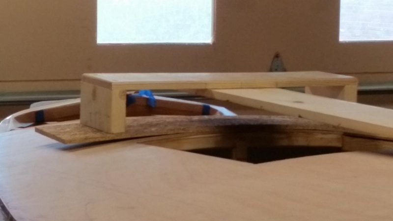
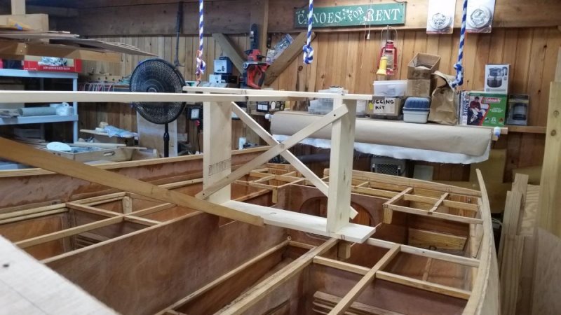
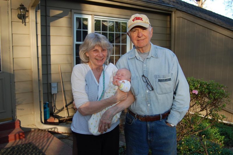
"Chessie" is ready to be rolled. It's setup for Saturday am. Here are a few photos of the support pedestals. It went together today. Pretty simple. When she's right-side-up I'll disassemble it for future use. The last pix shows Annie and me with our first GREATgrandchild. We now have 5 and another expected in February. "Chessie" is equipped with 3 "bow eyes"; one on the stem and two on the transom. She'll be rolled using a set of 3 pulleys, each with a x6 purchase. They will be set up tomorrow.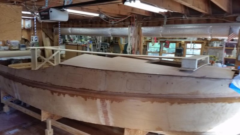
-
Core Sound 20 Mk 3 -- #4 "Chessie" . .
Pete McCrary replied to Pete McCrary's topic in B & B Yachts Forum
Actually trying a 3/8" semicircle with roundovered ends is a great idea. And easy to setup. Thanks, Ken. -
Core Sound 20 Mk 3 -- #4 "Chessie" . .
Pete McCrary replied to Pete McCrary's topic in B & B Yachts Forum
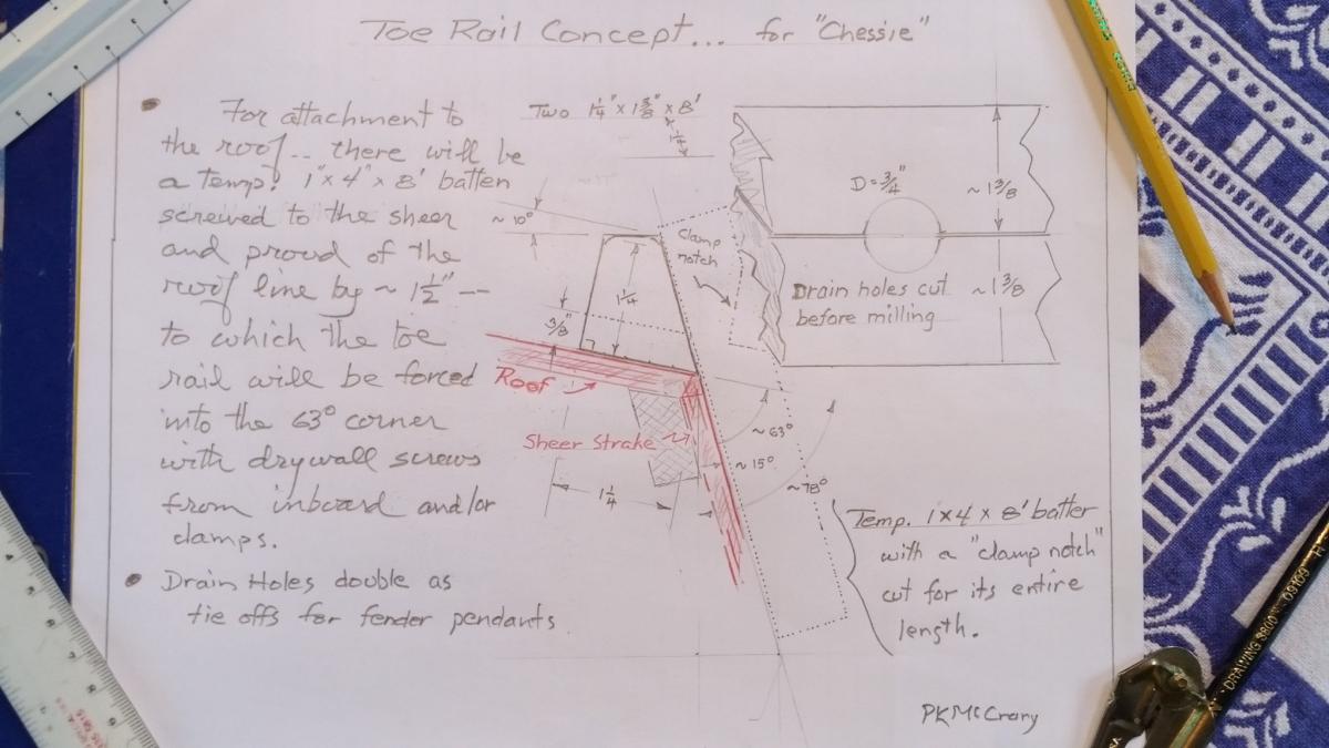
Thanks, Ken. The 3/4" diameter holes will not be subject to a saw kerf. The stock for the pair of toe rails will already be ripped to a xsection of 1.375" x 1.25" and will be clamped together for the drilling of the 3/4" holes. Besides the fact that a kerf won't subtract from the size of the hole -- the half-circles will meet at the roof line perpendicularly. For further ease (to a 1/4" fender pendant) the 3/4" hole will be rounded over (on the inboard side with a router) before unclamping the stock. I suppose the hole on the outboard side will have to be rounded over by hand after cutting the angle for the outboard profile. I've always used 1/4" line for fenders. However, the holes will have a length of 1.25". Considering all this, would you still recommend a larger diameter hole? -
Core Sound 20 Mk 3 -- #4 "Chessie" . .
Pete McCrary replied to Pete McCrary's topic in B & B Yachts Forum
Here's my concept for "Chessie's" toe rail. The drawing doesn't show the "bead" that I plan to cut (for the full 8' length) close to the bottom edge of the rail where it meets the sheer strake. Comments, suggestions, etc. welcome and invited. Especially as to material. I'm presently planing on using mahogany. It would be about the only thing that I would finish "bright." It would look pretty -- but would it be too brittle or soft ??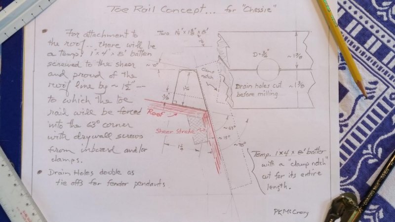
-
Core Sound 20 Mk 3 -- #4 "Chessie" . .
Pete McCrary replied to Pete McCrary's topic in B & B Yachts Forum
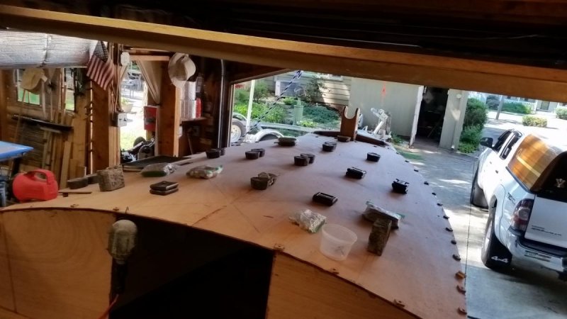
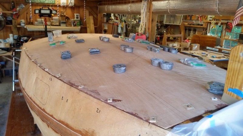
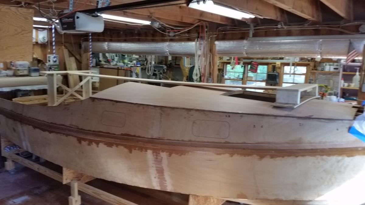
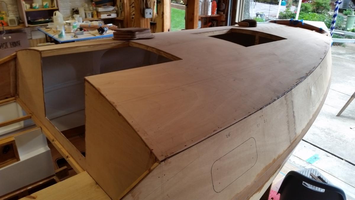
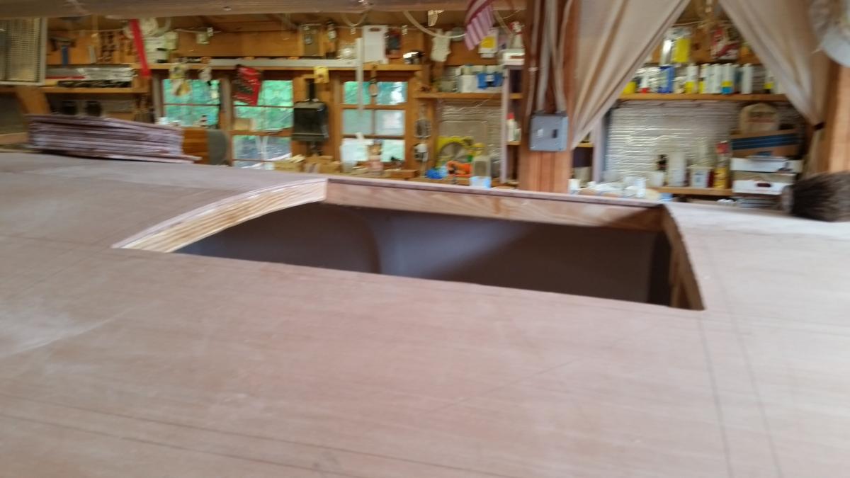
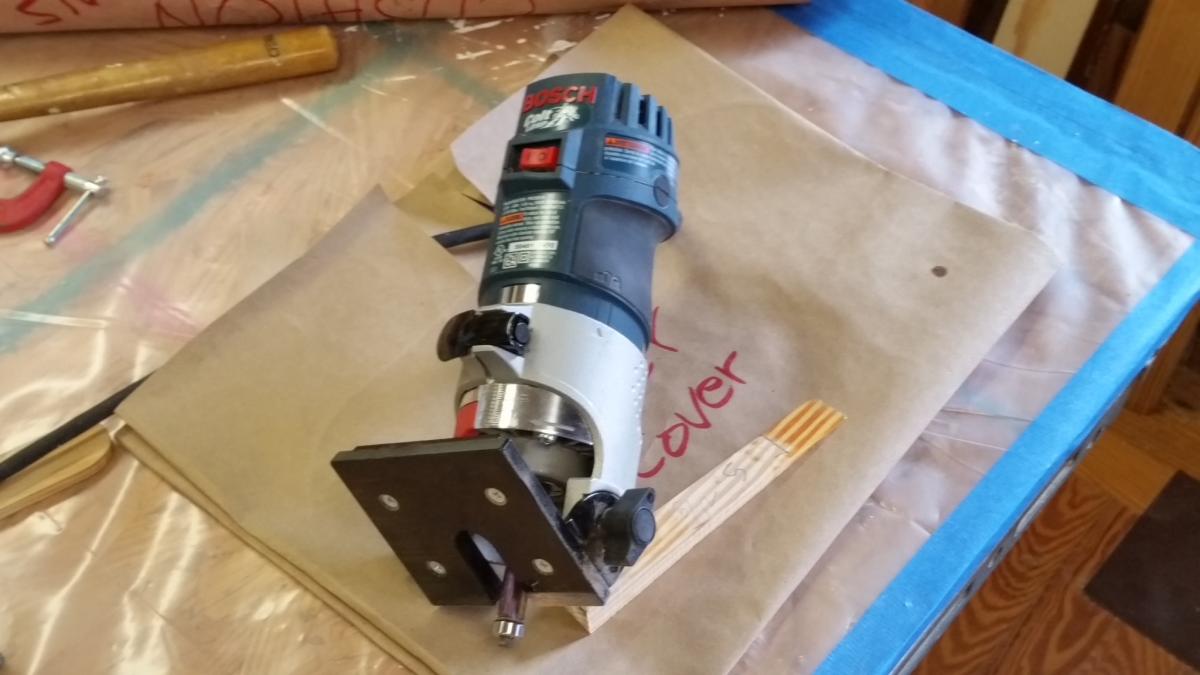
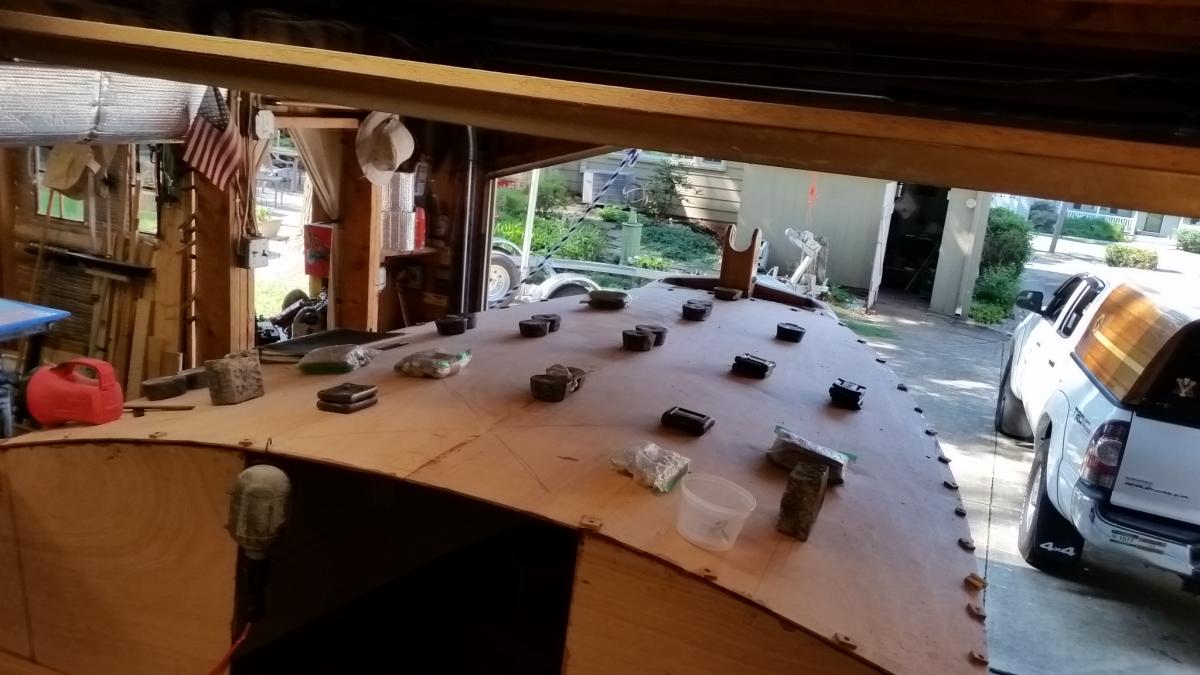
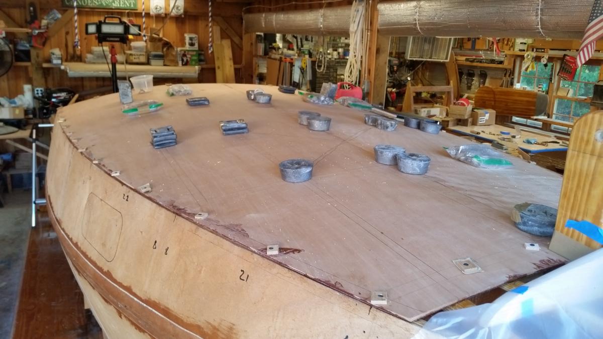
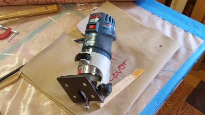
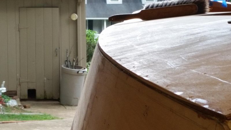
Here are photos of the cabin roof after removal of the weights and hold-down screws. And I have opened up the hatch and companionway. Next I'll perp the transom for glassing. . An indepensible tool for rounding over and trimming. Before building "Chessie" I didn't even know about this tool. If you are buying one, be careful that it has an attachment for "tilting" the base. Not all of them have that capability. I used the tool to trim the roof edge flush and inline with the the "extension" of the sheer strake. I won't roundover this edge because I will have the toe rail outboard edge be an extension of the sheer strake. It will have a small bead along the lower edge as an optical illusion to hide any small misalignments. It will also create a shadow that makes the viewer think the rail is lower than it really is. It will be a robust toe rail, high enough for limber holes to double as tie offs for fender pendants. When I have detailed its xsection, I'll post a drawing of it. The sheer strake -- cabin roof interface. I have a beautifully straight & clear piece of mahogany that is (in-the-rough) 2" x 8" x 8'. I've been saving it (several years) for something special. Perhaps it will be the only brightwork on the boat. Comments and suggestions would be welcome.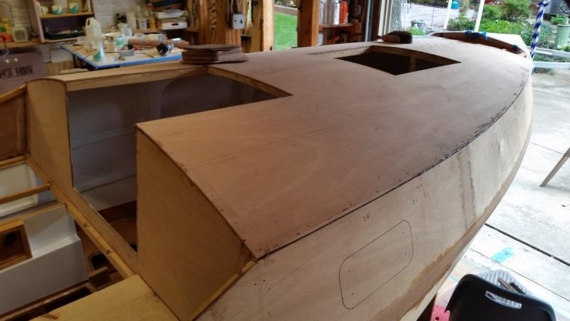


-
Core Sound 20 Mk 3 -- #4 "Chessie" . .
Pete McCrary replied to Pete McCrary's topic in B & B Yachts Forum
With one piece the "nice curve" comes naturally and [the curve] is maintained at the edges even after removing the plywood from the hatch and companionway openings. And, of course, the kit included the roof in two large half panels. I don't know how I would approach it if I were building from plans. -
Core Sound 20 Mk 3 -- #4 "Chessie" . .
Pete McCrary replied to Pete McCrary's topic in B & B Yachts Forum
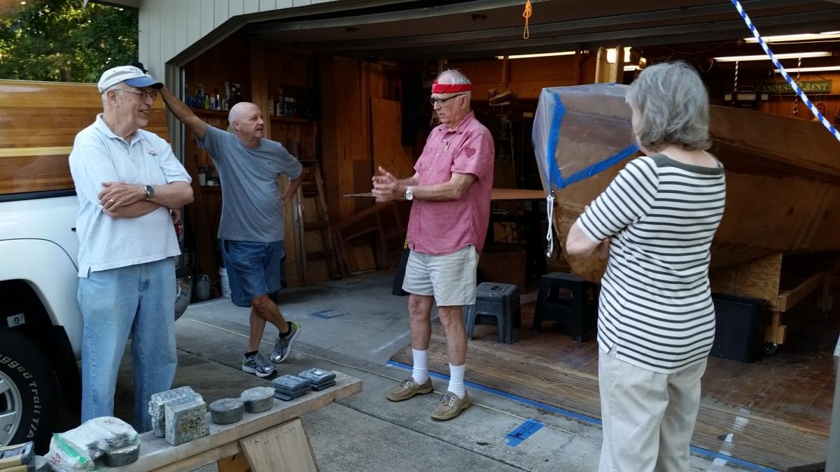
The roof is on !! Helpers Henry & Dale (neighbors) and Annie (my honey). I'm (third from left) explaining procedure before preparing the batch of thickened epoxy. We were scheduled to do this the previous afternoon, but canceled because of high shop temperature (98 degrees). Rescheduled for 8am today (outside at 71, shop 74). I'd show a video, but I can't figure out how to load it on to this forum. On the roof beams and inwales I put down a bead of thickened epoxy approximately (1/4" diameter). Small squeeze out around the outside edges. On the inside there was also a nice small squeeze out, no cleanup required. I mixed 6 pairs of squirts (B & B pumps) -- but needed two more in an extra batch. I figured I'd need 8, but was worried that an 8-sqrt batch would kickoff before I could lay it all down. I needn't have worried (temp @ 74 start, 78 finish). Tomorrow I'll remove the plywood material that now covers the forward hatch and companionway.