


Dave R1
-
Posts
1,132 -
Joined
-
Last visited
Content Type
Profiles
Forums
Events
Everything posted by Dave R1
-
Stump, you're welcome. So do you suppose there should be a smilie wearing glasses with white tape holding them together and a pocket protector?
-
How's this?

-
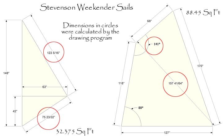
Alright, I'll admit I buried the needle on the Nerd-O-Meter. I just ordered new sails for Julie K and made some drawings to send to the sailmaker. I got to doing some rough calculating regarding the position of the reef row(s) The Weekender main calculates out to about 88.5 sq ft. Reefed at various distances from the foot, it looks like this 22" up---69.9 sq ft 30" up---63.6 sq ft 36" up---59.0 sq ft 44" up---53.1 sq ft I discovered that the sail plan dimensions don't quite work out right. If you use some of the dimensions, others don't match. They aren't too far off but might leave some scratching their heads. If anyone wants corrected drawings, I can send them.
-
Noel, I've been thinking about the idea of leading the sheet down at the aft end of the cockpit but with a wheel, I think this would be awkward. Or maybe it is me who is awkward. :? Wes, you're right about the PVC and I did have in mind to fix it in place. I share your concern about the gooseneck and have been thinking about that. It looks like PAR might have an easy solution. I was wondering about possibly mounting the blocks so that they could pivot on the centerline line of the horizontal portion of the mainsheet (or slightly above it). I have some ideas about how to do that but I suspect that it would be more complex than needed. The drawings are done in an application called SketchUp. Not really a CAD app., it is the brainchild of an architect who wanted a digital version on sketching on a napkin. It works quite nicely for woodworking and other things too. That picture and words adage comes to mind. It can output CAD files if desired. SketchUp is not as expensive as most 3D CAD software and it is considerably easier to learn and use. PAR, that chain idea is interesting. Thanks for that. Like I said before, I've been overengineering here. This is mostly an excercise but I appreciate the input. It might be that this would be a workable way to rig the mainsheet. Maybe not. I might give it a try if I can find some good wood for a hollow boom. I can always go back to the old one or at least a conventionally-rigged one if it doesn't work.
-
Jeff, Thanks for the comments. I'll take a look at the Precisions. I knew the angle between boom and sheet would need to be dealt with but this drawing was a start. I've thought about having the mainsheet come down forward of the cabin hatch hatch but I'd have to build some sort of bridge to clear the hatch when it slides foward. My feet get to be about 4 sizes larger when I get on board my boat and that bridge would take up valuable foot space when I'm raising or lowering the mast. I'm kind of avoiding going up to Lake City right now. There's an Irwin 34 waiting for my attention up there but I don't want to even look at her right now. I'd love to have the space to rig my boat now so I could do some tuning and stuff. Unfortunately, the boat is stored elsewhere while all the spars and rigging are at my place. I need to find a heat garage with about 24' of ceiling height. Not likely here in the Mayoville.
-
Thanks for the replies. So far I've had good luck with my 1/2" sheet but I might go down to a 3/8" one to reduce the mainsheet block size. Those hanging on the boom have a fair amount of mass. There's a mark that some student pilots wear on their foreheads called the "Cessna Star". It comes from walking into the trailing edge of the wing which, due to the stiffening creases in the aluminum, leaves a diamond-shaped mark. I was warned about that and never got one. I do think I might have a "Harken Crescent" on the back of my noggin, though. So, I've been overengineering again and this is what I have come up with. The idea stems from a thought of having a bimini over the cockpit to keep from cooking the crew quite so badly. Ian, my little midshipman, is so fair that he gets sunburned looking at a picture of the sun in a book. Well, maybe that is a bit of a stretch but not by much. I want to gain as much clearance under the boom as I can get and I thought this might help. Of course this idea might not go anywhere, too. A new boom built using the birdsmouth method. The two side staves are wider to give an oval section. A pair of through deck blocks let into the underside of the boom lead the mainsheet foward inside the boom instead of allowing it to hang below. A piece of PVC pipe in the boom between the blocks provides a smooth guide for the line. There's still an important detail to work out or if not resolved might send this idea to the recycle bin. The lead of the line is fine as long as the boom is on or near the centerline of the boat. It gets a little iffy when the boom is swung out. A boom that can roll at least a few degrees might be the solution of maybe setting the blocks up to roll a bit from side to side is the ticket. Here's the drawing so far.
-
Adla, I just thought I'd relay a couple of things I came across in The Sailmaker's Apprentice related to reef points. "On boomed sails with a fixed foot [as opposed to loose-footed] the corner rings must be positioned above the straight-lined reef row so that they take the primary strain. A good guide is to start and end the row of eyelets a ring's diameter below the corner ring. If the rings are of different sizes, use the larger measurement of the two." "Quite simply, the reef row on a boomed sail with a fixed foot can be perfectly straight, the idea being that in heavy winds you want a flat sail anyway..." Regarding reef point patches shown in the Apprentice are either diamonds or squares with a point up. For a diamond-shaped patch the author shows 3" between parallel sides; for squares 2" is the given dimension. A patch is sewn on each side of the sail. the cloth direction must match the direction of the sail. The author prefers to sew a reef band instead of individual patches because this can more easily and quickly be done with a sewing machine. He says, regarding the eyelets themselves, "Eyelets should be no farther than 2 feet apart, even on large boats. On sails of 100 square feet or less, I place them every 12 to 14 inches. Try to have a measurement and a spacing that avoids disproportionate gaps at the forward and after ends of the reef row" Hope that gives some guidance.
-
Foam? What foam? I didn't see anything in the instructions from Sailrite about foam. I knew the hanks wouldn't be used but the grommets at the tack and head appear to be used for the stitching used to hold the luff wire in place. Did you just stitch through the fabric instead?
-
Barry, I think I need some clarification on what you're saying. By "grommets" do you mean hanks? The jib only has three grommets, one at each corner. The polytarp jib I have now has the nylon hanks but last summer, I added a temporary luff wire to use it with the roller furler. I left the hanks in place because I wasn't sure if I wanted to eliminate them. As far as the wrinkles running parallel to the luff, on the polytarp jib, they wouldn't shake out even in a strong breeze. I'm not so worried about wrinkles in a dacron sail because they aren't so obvious. The Sailrite instructions show installing hanks after the luff wire. Are you suggesting I skip the hanks altogether? By the way, to make sure we have the proper terminology here, These are what I'm calling hanks: And these are what I'm calling grommets: http://www.duckworksbbs.com/sailmaking/grommets/CHG_B&N_2&4-big.jpg
-
Just wondering what folks are using for their mainsheet. I've got 1/2" which is comfortable to hold but I'm toying with an idea that I'll share later. It might require a smaller diameter mainsheet, though.
-
Craig, you can call me anything but late for dinner. Barry, are you saying I should leave out the grommets at the tack and head of the sail? FWIW, you can see the wrinkles in the jib in this photo. Pretty ugly if nothing else.
-
Thanks Charlie, I'll try calling them. I wondered if they would be busy. I thought if they were, it would be nice to let me know in the one brief e-mail I got. Well, we'll see what they say. thanks again, Dave
-
I'm thinking about a new jib for Julie K this year and figure I'd better get started. The sails I have are Paul's Polytarp stuff which works alright but the jib gets some unsightly wrinkles after being rolled up with the roller furler. I was thinking I'd order a kit from Sailrite but I wanted to know what modifications would be required to set it up for roller furling. Although their Weekender Jib kit instructions show the installation of a luff wire, it also shows installing the hanks for clipping it onto the forestay. I'm trying to find out if there is anything else I need to do or order to make the sail suitable for roller furling. I e-mailed Sailrite and after a couple of days finally got a response asking what kind of roller furler I have, I replied to that and haven't heard a word since. Makes me wonder if I'll get an answer and if I'll get my kit in time to make the sail before the water gets soft. Has anyone dealt with them? Does anyone have first hand experience with one of their kits and especially setting their jib kit up for roller furling? By the way, I'll keep the forestay so a larger diameter luff wire wouldn't be needed for for strength reasons. Maybe there's nothing additional to do?
-
The ball on the front isn't a bad idea from a maneuvering standpoint either. Sure would make it easier to run the trailer around. My FIL has a ball on the front of the 8N and his little JD lawn tractor for moving boats around at the cabin. Sure is slick. Around here I think you'd get strange looks at the boat landing though if you took the time to turn your car around before pushing the boat down the ramp. Hey to Mike D. How's it going?
-
Greg, I just sent it.
-
Bill Paxton built Surprise without a cabin. Very good idea and he's got an excellent boat. Bill's on the right.
-
Howard, your test joinery looks very good but I would suggest some caution and perhaps a bit more math before you build an entire mast or other spar using the bit you used for your test. The resulting wall thickness in your example isn't very much. If you stick close to the scantlings given for a solid mast, you may find you don't have the needed strength or stiffness. I have a section in my Excel-based birdsmouth mast calculator that gives a rough comparison of strength between a solid spar and a hollow one. Unfortunately I think the calculator is at work so I can run any numbers right now. In any case, please do some investigation before you go to the trouble of making a twelve-sided mast. Good luck with it, though.
-
I've not seen the plans for your boat but I used a router for quite a number of things when building my Weekender. When I made the keel, I shaped one of the three layers, rough cut the other two and used a router with pattern trimming and flush trim bits to bring those two layers down to the first one. Because I cut the side panels flush with the deck, a router worked great for that. I had to make a little guide to attach to the base plate because of the angle but it worked fine. I made a pattern for the windows and used the router to cut those. I cleaned up the hole in the deck for the mast with the router. Easing edges has already been mentioned. I used the router in a table for a number of operations. I even turned my bowsprit with the router. There are a bunch of little trim pieces that saw the router, I used it to cut flats on the sides of the boom for the goose neck. There must be things I'm forgetting. Alot of things could have been done without the router but it sure made life easy for many of them. So to add to your collection, I'd say a flush trim bit and a pattern trimming bit. These bits have a bearing at opposite ends. They come in hand for a number of things. I'd also consider adding a rabbeting bit but the size will be dependent on your needs.
-
At the same time? Sorry, couldn't resist.
-
Noel, if the glue joint is made properly it will be stronger than the wood. There shouldn't be any problem with using scarf B in a compound curve. The one problem might be that the piece might have a hard spot where the scarf is and wouldn't make a smooth, fair curve.
-
I think B makes more sense for solid wood because it creates a joint that is much closer to being a long grain to long grain joint and because the faying surfaces are so much larger. A makes sense on plywood though.
-
Jake, one of the problems with the dovetail jigs out there is that they are set up for only one sort of bit or maybe even only one bit. The ones with the fixed comb sort of guide are rather limited and if they only have the parallel-sided fingers they can only do half blind DTs. I didn't use a dovetail jig to do this joint although it was done with a router. I used a device called the WoodRat. It is kind of like a router table except the router is right side up. It can be used for all sorts of stuff besides dovetails. Since both the router and the work are being held by the Rat, you can do safe climb cutting which yields better, cleaner cuts for things like tenons and edge profiles. Climb cutting on a conventional router table is a great way to lose some flesh and squirt blood all over your shop. the Rat isn't limited to a specific sort of dovetail bit. you can use carbide bits if you want although I certainly prefer the look of the HSS cut joint. It is much closer to looking like the needle pins you might cut if you were doing it by hand. Here is a picture and some drawings I did of the Rat. The drawings show a piece of blue T-track. this is my modification and I ended up using a different sort of track which you can see in the photo. In the photo, the router is to the right just out of view In these drawings, I omitted the router and the parts associated with it for clarity. they were done to illustrate the use of the stops and the T-track. Here's a link to the US distributor of the WoodRat http://chipsfly.com/ Take a look at the Plunge Bars, too. They are a cool attachement for the router with or with out the Rat. Go to http://woodrat.com/ and click on 'See it in action' to see a video clip of the Rat in use. the guy in the clip is the inventor. While the Rat might seem expensive for a dovetail 'jig', consider that it is also a mortiser, a tenoner, it does box joints, sliding dovetails, profiles edges, cuts rabbets and dados, makes dowels, raised panels and basically anything else you'd do with a router table. I used mine to cut flats on the boom for my Weekender to receive the arms of the gooseneck. I think it's a cool machine.
-
I just thought I'd share a picture of a dovetail joint I made today. This was a test joint to test a stop system I came up with. Thesockets were cut with a router in 3/4" stock with a HSS 8
-
Looks like you had a great time. Thanks for sharing that with us. It snowed here today.
-
Can I come? Have a great time. Make sure you take lots of pictures and tell us all the details when you get back. For some of us the water is much too hard to sail in.

