Graham
-
Posts
7 -
Joined
-
Last visited
-
Days Won
2
Graham's Achievements


-
Here is how I do i t on Carlita. I could not find a picture where I had done a neat stow so you get to see my slovenly ways. I have an eye strap on the forward side of the mizzen mast which is about 4-5 ft. above where I would like the aft end of the main sprit to stow. There is a small line tied the eye strap with an S hook at the bottom end of the line that hooks on to another eye strap on top of the aft end of the sprit. It takes me about a second to attach the S hook to the sprit after the sail is lowered. The sail drops to the sail stop at the bottom of the track. I put three sail ties in my pocket and go forward and roll up the sail and put on the first tie, working back tying the other sail ties. I then tighten the snotter to take the sag out of the sail and tighten the main sheet. If you don't tighten as above, you will definitely get woken if waked during the night as the sprit bangs against the mast. I use the mizzen staysail halyard as a topping lift to hold the aft end of the mizzen sprit where I want, otherwise it is the same as the main stow.

-
Decisions, decisions or analysis paralysis!
Graham replied to David Wrate's topic in B & B Yachts Forum
Hi David, Yes, the Belhaven has a lot more interior space than the CS17 mk3. I positioned an updated CS20 mk3 which has more cabin height than the 17, on top of our newly updated Belhaven and sliced off the outboard couple of feet so that you can see the space difference on center and at the quarter beam. The B19 is green. The CSmk3's were designed for beach cruising and events like the Everglades Challenge where you need to be able to row. The water ballast can be added or subtracted to enable beach launching, be lighter for light air performance and towing with a smaller vehicle and sail in very skinny water. I have dragged Carlita all over the country with a 1.9 liter vehicle. The Belhaven was designed as a normal trailer sailor and has more freeboard and a shorter cockpit. There is no bridge deck making it easier to go below. The bunks are about 4" higher making sitting a bit more comfortable. The plans were drawn way back using 2d CAD making it not accurate enough for CNC cutting. We have been updating her starting with 3d modeling her hull. The cabin was raised a couple of inches by one owner so we raised the freeboard by 2" while we were at it.
-
That is an easy fix. At the forward end of the sail I see that the sail slides below the reef have come out of the sail track. I cannot see a sail stop / gate in the picture. You need one on each mast to keep the slides contained on the track so that the sails are neat and tidy. At the aft end; before you roll up the foot of the sail, grab the clew and pull it forward so that the leech is paralell to the reef. The fold should be at about 45 degrees from vertical. You can now roll the up the foot of the sail and and tie off the reef points. It should look neat and tidy and be able take normal sailing stresses in strong winds. If you do not have sail stops, there is a drawing with dimensions. on the mast plans. You can make them out of a plastic cutting board. I know of a few kitchens that have a small corner missing and no one knows the difference, after the edges have been smoothed over and corners rounded to match the board. Or you can buy them from B&B. We should have a picture of the reefing procedure somewhere. If this is not clear I will try to get one.
-
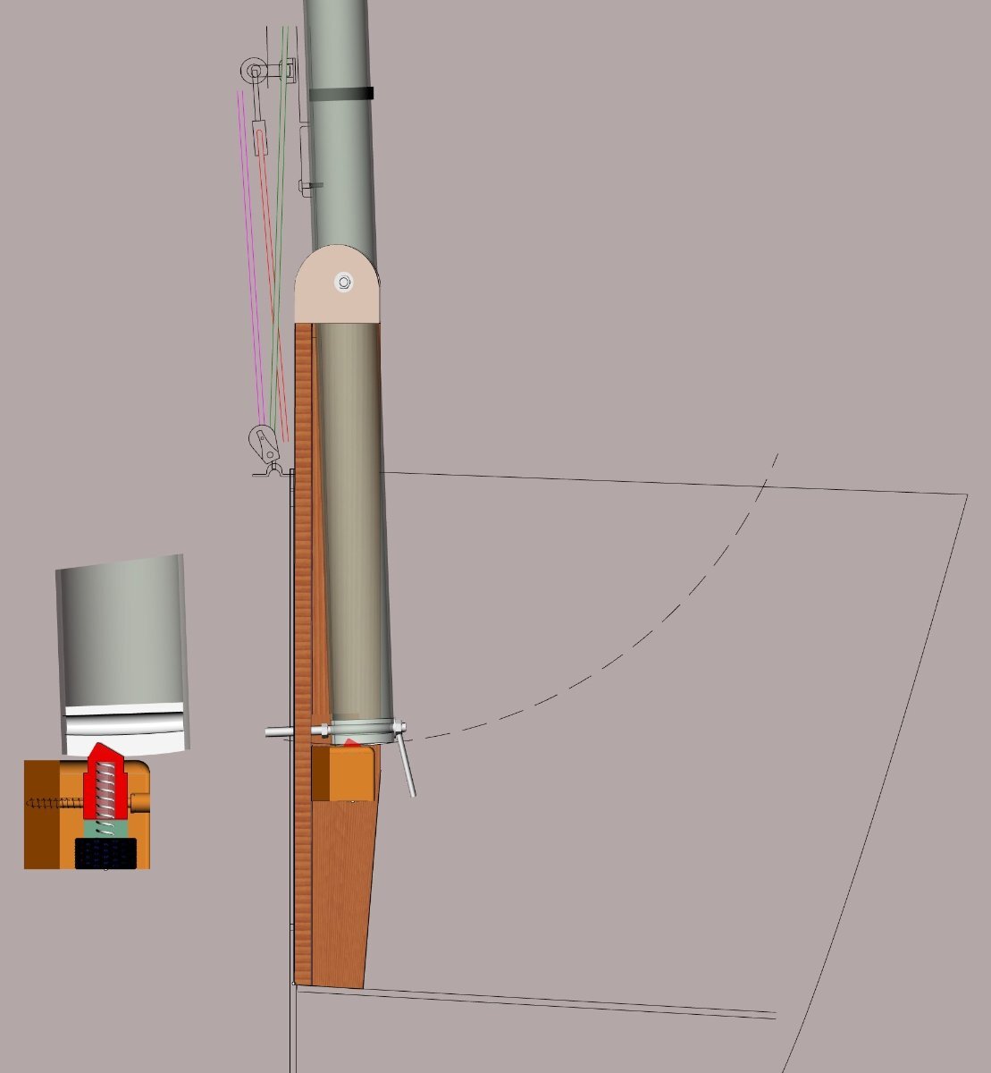
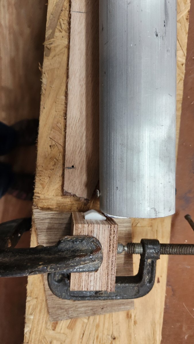
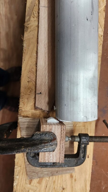
Carlita's mainmast is very easy to raise single handed, except for spinning on the handle nut to lock the heel in place. The trick is to prevent the mast from rotating aft with my right hand reaching as high as I can with my right arm while trying to spin the handle nut on the forward facing bolt at the bottom of the mast that is out of sight with my left hand at full stretch. I have never failed or had an accident so far. Sometimes it takes a few attempts and it seems to be getting harder. One of my concerns with this multi tasking is that while I am concentrating on trying to keep the nut in plane, perpendicular to the thread axis to get the thread to start, with it's long one sided angled handle arm, I not keeping up the force with my right hand. What if I start to relax my right arm while I am engrossed with the bolt and the mast is heading south before I am aware? Our good friend the late Peter McRary was concerned about it on his CS17 mk3. He rigged a temporary forestay just for mast raising. It worked but I don't want any more jobs or clutter to add to my rigging and unrigging. My demands were: It had to be automatic, no clutter, out of the way and reliable. Easy to unlock when unrigging. I chose a force of about 10 pounds at shoulder height to unlock. My first design started with a piece of sail batten for a spring and a wedge. It would have worked well on mast raising but It would have required reaching down under the mast to release and start to lower while bending down. I could have run a line and cleat to release from on deck but I ruled it as clutter. Here is what I came up with. The temporary lock is located below the mast. It has a spring loaded plunger (red) that is pushed down by a 3/4" wide plastic striker(white) running fore and aft in the mast heel that has an indent to hold the mast in place while I spin on the handle nut. The dark brown block is a spacer to position the plunger in the right place. The green part is the channel that the plunger travels up and down in. The dark blue part is a threaded cap that screws in under the spring that allows for assembly. There are 2 2"#10 pan head screws holding it all in place. The cut away view is scaled twice normal size for clarity. The picture was a quick and dirty test model to prove that it would work and test the release force. All I have to do now is to hold Alan down long enough to feed it into the 3d printer.

-
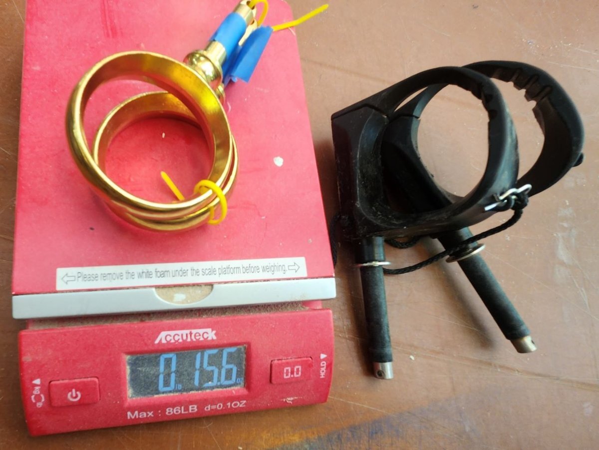
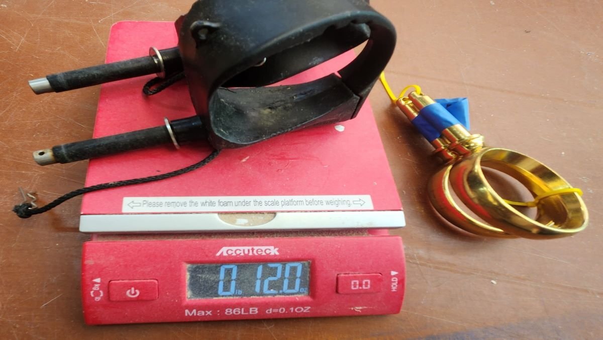
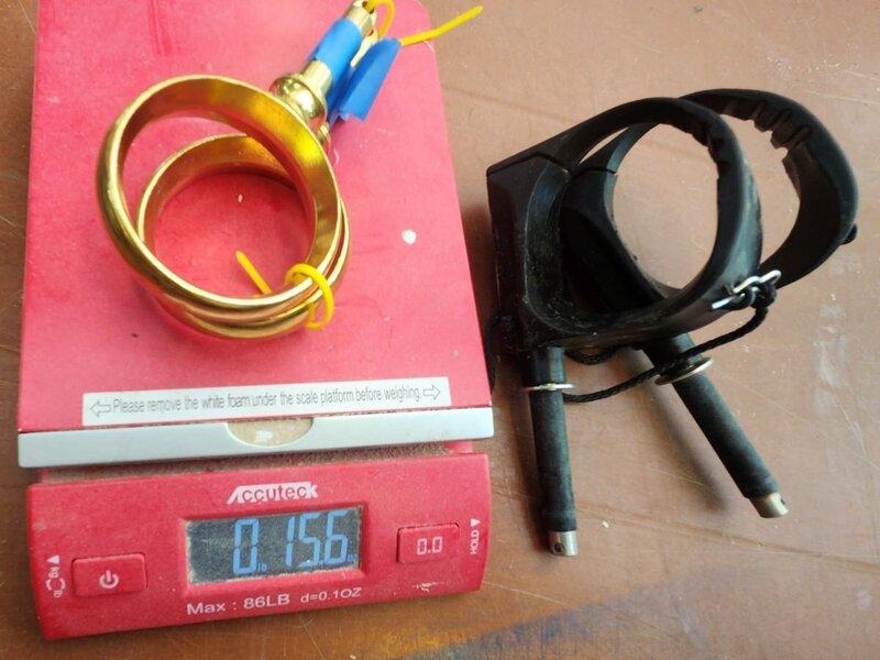
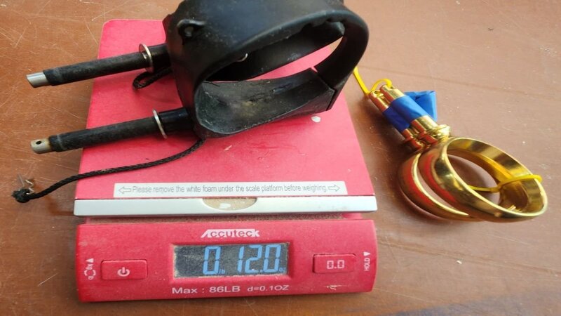
You are doing a nice job on your Spindrift. I decided to weigh a couple of oarlocks that were handy. The bronze oarlocks are 2 1/4" which we usually use on a Spindrift and the black ones are the Gaco that Don recommends. I have never used the Allen all plastic rowrlocks even though I have had some laying around. The Gaco look well made, has almost no friction and quiet. Time will how long they last. I bought them because my left arm has lost a lot of strength and aches after a hundred yards rowing a Catspaw. The ache comes from having to grip the left oar harder proportionally than my right hand to get the blades to strike the water at the right angle. On the Gaco the oar bears against the pivot post on the pull stroke so I built up a flat surface on the oar out of thickened epoxy to what I thought was about the right angle. I have not really tried it out yet but Alan's mom Dawn used them a lot on Carlita in the last EC and said that they worked ok. If the only reason to change was to save 3.6 ounces probably would not.
-
Mast Raising onto Pin Problem, Core Sound 17.3
Graham replied to Jonathan M. Cohn's topic in B & B Yachts Forum
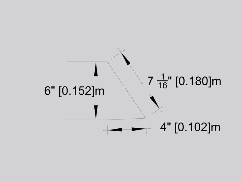
You should not have to fight with the bolt every time you raise the mast. You just have to get the geometry right. The mast swings through a 17 1/4" arc between the hinge bolt and the center of the bottom bolt. Over the 3" mast diameter, the hole needs to be elongated an extra 1/16" vertically or it will bind (see the green lines). Remember that this is all hand made so the fit will have to be finessed. The bottom bolt is angled 2.4 degrees above horizontal. Carefully cut a triangle out of cardboard with sides 6" x 4"x 7 1/16". Position the 6" side up the tabernacle and the 4" side on the bolt to check if it is angled correctly. If it is close I would get a 3/8" round file and drag that mast hole up or down until it goes easily. If the bolt was way off which is unlikely because you have already had the mast up. You could heat the bolt until the epoxy softened which is about 140 degrees take the bolt out and epoxy it back in to the correct angle.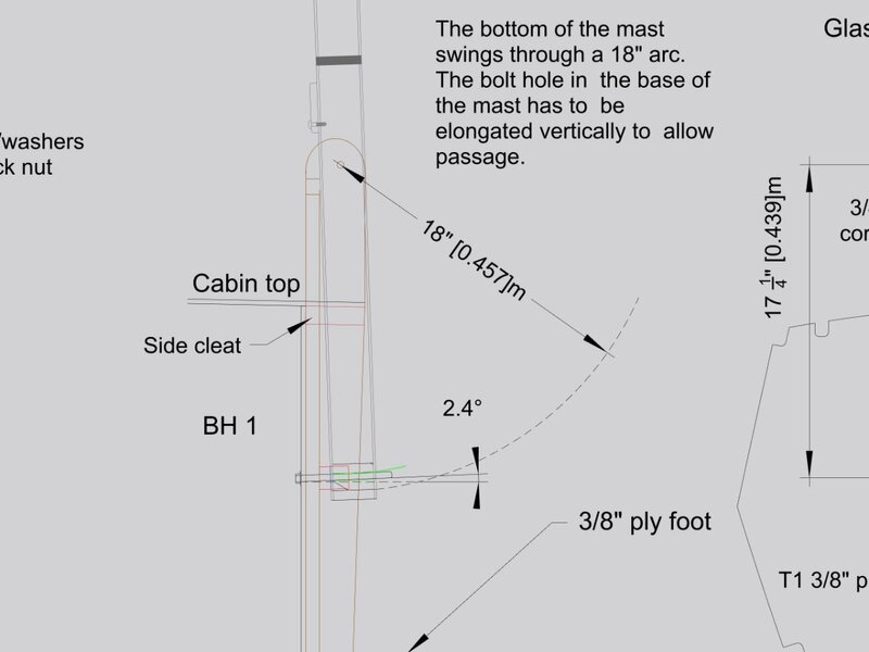
-
Hi Jan, Can you hold off on the mast until I check the shop computer tomorrow. I was under the impression that the S12 mast plan was updated. My home computer is showing a mast that I updated in 09. We have gotten rid of the wood mast heel plug and replaced it with a plastic heel which changes the length of the aluminum sections.