

J. Cote
-
Posts
66 -
Joined
-
Last visited
-
Days Won
1
Content Type
Profiles
Forums
Events
Gallery
Posts posted by J. Cote
-
-
5 hours ago, Designer said:
I am glad that the confusion has been cleared up, maybe I can muddy the waters a bit more by discussing how to use those controls.
I have recently wondered if we are doing anyone any favors by having the adjustable outhaul when most of the time most people either do not know how to use it or are using it wrong. The most egregious act is to leave off the red line which acts as a cheap version of an outhaul car by keeping the the clew close to the boom and leaving the outhaul to just haul the clew out or in. When the red line is not used, the outhaul can only raise or lower the boom. There is never any need to lower the aft end of the boom as it just brings the boom closer to your head and makes it harder to duck the boom during a tack. It also tightens the leech and drafts the foot too much making the sail set inefficiently.
We only have 4 sail controls. Mainsheet, boom vang, outhaul and downhaul/ halyard. The downhaul is on non reefing sails and the halyard is for reefing sails. To save duplication I will just use downhaul for both rigs.
The mainsheet obviously brings the sail in or out but it also controls leech tension and mast bend which effects upper sail draft when close hauled. The outhaul effects the draft of lower region of the sail. the downhaul effects the draft in the forward part of the sail or luff. The boom vang controls sail twist when the mainsheet is eased.
When sailing to windward in light air I have no downhaul on and I want the outhaul to give me a modest camber in the foot area of the sail and a slightly eased mainsheet and eased vang. As the wind increases the sail draft starts to move aft so downhaul will be tightened and the mainsheet will be brought in and the outhaul maybe tightened. When I bear away and I don't need to point, I start to power up, as I ease the mainsheet I let out a lot of outhaul, the downhaul will be eased unless the wind is strong. I start to bring on the vang if the is much wind, being careful not to over tighten the leech. When I get to a broad reach, the sail stalled and is no longer an airfoil, I switch to the maximum projected area by tightening the outhaul and downhaul as much as I can.
When racing I will pull on the control lines many times and it really helps improve your performance when you get it right but if you are out sailing alone all of this could be as meaningful as shouting while alone in the forest.
Huh?......

Sorry Graham, I think I'll have to read this a dozen times while staring at the drawings before I have even the slightest clue what you're talking about. I'm sure I'll have to sail the boat for a while before I truly "get it". I'm going to save your quote for a "smarter Jan" in the near future.
-
14 minutes ago, Alan Stewart said:
Janice,
The confusion here is because Don substituted the raacelite 340 block that joe pictures for the ball bearing Ronstan RF20151 cheek blocks on the hardware order. So the one you used for the halyard is the same cheek block that you'll use for the outhaul. We emailed about this back in January but I had to re-read it to see what we did. BUT It had looked like you were missing one of the Ronstan cheek blocks you needed (1 for halyard, 1 for outhaul) and I was supposed to send you a second one along with those other items we discussed. I may have forgot so if you don't have 2 of the RF20121 cheek blocks then I probably did and can send you one right away.
Those screenshots from the boom plan are from the old rigging plan sheet but they are still in the plan. We updated all the Spindrift rigging sheets over the last few years. The boom end is shown in 2 places. One on the Rigging overview sheet and again on the boom detail sheet.

Thanks Alan. I'll get acquainted with your schematics & description above and get back to you via email. This is helpful.
-
1 hour ago, Joe Anderson said:
I am sure Graham or Alan will get back to you.
In the mean time the RL 340 cheek block(if that is what is included in your kit) does not look like much. It is small and the pulley part can become separated so it can be a little difficult to pick out of a bag of hardware. Maybe you have it.

If anyone asks I lifted that photo from the Duckworks web site.
Nope, don't have one in my kit or in my invoice list, Let's see what Alan/Graham recommend. Thanks for the photo.
-
1 hour ago, Joe Anderson said:
Graham weighed in earlier and mentioned the cheek block sooo.
Granted omitting the cheek block would cause more of a problem on the reefing line as it has to go forward and up and over the tack and down to the base of the mast. The clew is just cleated on the boom.
Graham has little tolerance for extraneous complexity or weight. If that cheek block wasn't earning its keep I think he would have removed it from the plans.
Normally I set the outhaul tension when I am setting up before starting to sail. In that situation you could probably get enough tension on the outhaul despite the extra friction of the eye strap. however once underway getting proper tension is much more difficult. There have been times when the outhaul line has come out of the jam cleat or I have forgotten to tension it or I want to adjust the tension underway. Then I am grateful for the cheek block.
If you are using the 073 eye strap with hole spacing that matches the cheek block than theoretically you could later easily replace the eye strap with a cheek block, but if the hole spacing does not line up you will have an issue. I did not see the RL 340 cheek block on the Racelite web site. If you got a hardware package from B&B. Perhaps Graham or Alan will chime in and give you a definitive answer.
Thanks Joe. Alan & Thrilsbe collaborated on my hardware at a time when I didn't know what any of this stuff was, let alone where it goes. I just recently opened the bags to figure them out. Alan/Graham, what do you think?
-
1 minute ago, J. Cote said:
Thanks Joe. I don't have that top view section or that page in my S12 plans. Now that you showed me a cheek block, I know what that is & I don't have that either.
I am not doing a reef line, so that may be why my hardware is different. I have eyelets, so I think I should bolt eyelets on the port & starboard sides, across from each other & share bolts. I'll tie the outhaul line to the port side eyelet & use the starboard eyelet as a cheek block. Do you think that will be OK?
-
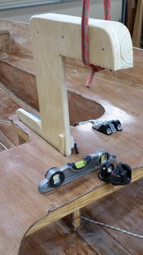
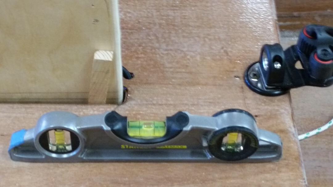
7 hours ago, Joe Anderson said:
I think this is the view Graham is referring to eye strap is on the port. cheek block is on the starboard. It looks like the sheet block hangs from a separate eye strap underneath the boom. The tip of the boom is very busy with fasteners. Some are running at right angles to each other. Sharing fasteners cuts down on the clutter. I think I had to adjust my eye strap a little to get it to line up with the cheek block. Very careful drilling is in order. You may even want to practice on a scrap of wood. I think I ran my sheet block to the center of the boom instead of the end.


Thanks Joe. I don't have that top view section or that page in my plans. Now that you showed me a cheek block, I know what that is & I don't have that either.
I am not doing a reef line, so that may be why my hardware is different. I have eyelets, so I think I should bolt eyelets on the port & starboard sides, across from each other & share bolts. I'll tie the outhaul line to the port side eyelet & use the starboard eyelet as a cheek block. Do you think that will be OK?
-
On 11/7/2020 at 12:49 PM, Pete McCrary said:
Now I can “flip” Seabiscuit as well as lifting her. Here are the photos:

Level side-to-side. Note wedge forcing lift-vector to starboard a little.

Pretty close to level fore-to-aft.

Under, looking to starboard.

Looking to port.

Hanging by a thread(s?).

C.G. about 5” aft of CB Trunk.

A loop thru a pulley. Ready to be flipped, starboard down. I rotated her about 45 degrees (1/4 of a half-roll) with ease — but stopped there because the cradles weren’t yet rigged for a top-down boat.

Now I’ll drop her top-side-up and mark the waterline. Then flip her for masking and painting the boot (red). Haven’t decided whether to leave the bottom with just the AwlGrip 545 primer— or use the Interlux Sea Green that I have. It won’t be any anti-fouling paint.
Hope to get in one more sailing day this year. Looking for a warm day!

Very clever! I appreciate your photos. I'm finishing an S12 now & you've taught me a few things.... like how you attached the halyard & gooseneck so that your mast will still nest for storage. Your photo of the end of your boom answers another question I had about how to route the outhaul line. Thank you!
-
12 hours ago, Designer said:
Hi Jan,
A Harken eyestrap goes on the port side of the boom for the outhaul. There is a drawing from the top view showing how the cheek block and eyestrap share the same fasteners.
Hi Graham, I looked through all my plan sheets carefully & couldn't find the top view you speak of.
So there is an eyestrap on both sides of the boom?
If that is the case, I can picture the 2 eyestraps sharing "bolted fasteners", but I can't picture the beckon block & eyestrap sharing fasteners because they are at right angles to each other.....
-
13 hours ago, PadrePoint said:
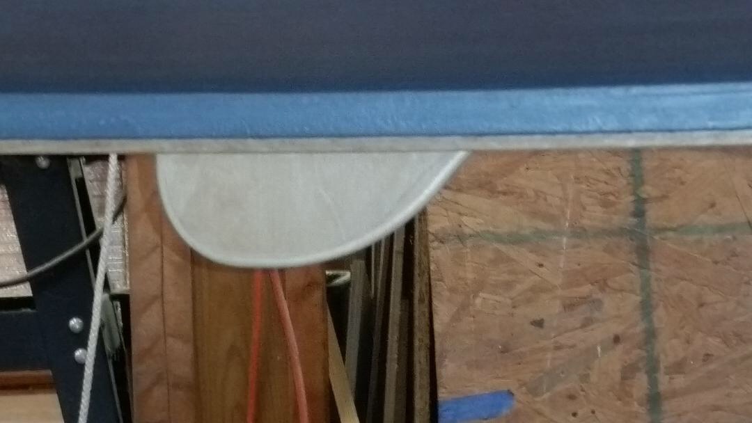
From Spindrift 10 plans... it looks like an eye strap could anchor the blue out haul line on the port side.
The red line is an extra loop to pull straight down on the clew. Does this help?

Thanks, I have that same view on my plans, but it just shows the line going behind the boom. I suppose an eyelet could be back there to run & knot the end of the line through.
-
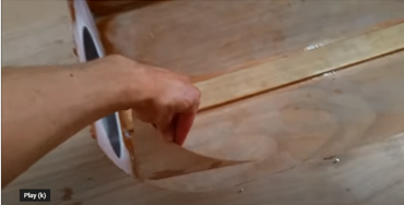
How does this out haul line attach to the boom on the port side? Or does it?

-
9 hours ago, J. Cote said:
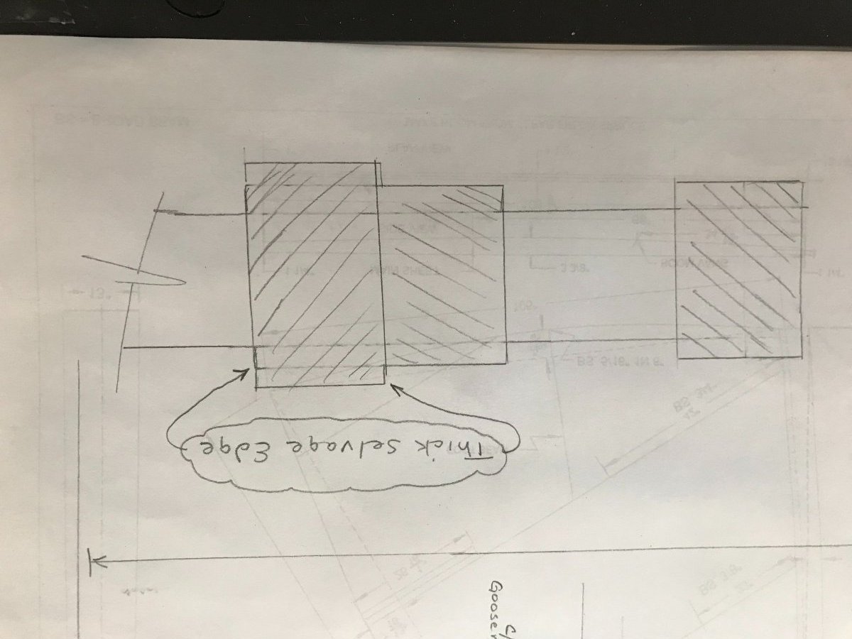
Thank you Pete & Hirilonde for your descriptions. Did you pay attention to the FG thicker selvage edge? My impulse is to position them as shown....

Actually, I think I answered my own question. I'm going to remove the thick selvage edge from the top 3" wrap so the taper is more gentle. Thank you all for helping think this through.
-
39 minutes ago, Pete McCrary said:
I think Dave has it right. If you want to separate the tubes for transport, you'd never insert the tubes while any epoxy is not yet cured. Dave made his bushings one layer at a time until just a little too big, then sanded down to a proper fit for steadiness and ease of separation.
My procedure was to wrap (modestly tight) the smaller tube with FG tape (end secured with masking tape) until the thickness was just the ID of the bigger tube (measured with a "mic") -- then [I would] lay out the FG on bench (surface covered with packaging tape) and wet it thoroughly with epoxy. Then lift it off the bench and wrap it (keeping it taut) on the tube. After cure, the thickness should be slightly more (than measured) because of the epoxy. Then sand to the fit that you want. Worked OK for me.
Thank you Pete & Hirilonde for your descriptions. Did you pay attention to the FG thicker selvage edge? My impulse is to position them as shown....
1 hour ago, Pete McCrary said:I think Dave has it right. If you want to separate the tubes for transport, you'd never insert the tubes while any epoxy is not yet cured. Dave made his bushings one layer at a time until just a little too big, then sanded down to a proper fit for steadiness and ease of separation.
My procedure was to wrap (modestly tight) the smaller tube with FG tape (end secured with masking tape) until the thickness was just the ID of the bigger tube (measured with a "mic") -- then [I would] lay out the FG on bench (surface covered with packaging tape) and wet it thoroughly with epoxy. Then lift it off the bench and wrap it (keeping it taut) on the tube. After cure, the thickness should be slightly more (than measured) because of the epoxy. Then sand to the fit that you want. Worked OK for me.
-
On 11/11/2020 at 7:40 PM, Pete McCrary said:
Today the boot got its 2nd (and) final coat of Interlux Brightside paint. Tomorrow I’ll mask the entire boot and apply Sea Green for the bottom and White for the topsides. Note that the color scheme will include the CB and Rudder Assembly. But the rudder itself will be left showing its last coat of neat epoxy.


There will be a line painted on the CB so as to show (above its trunk) when the end of the CB is positioned just at the keel.
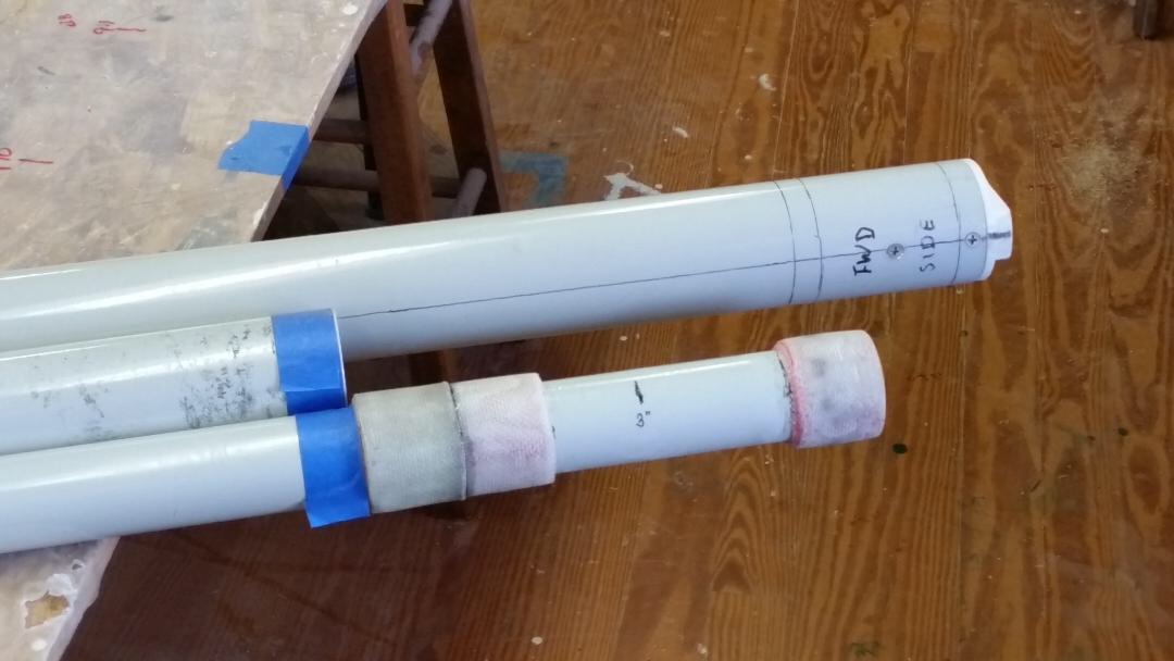
Below are a few pixs showing a nuisance problem when transporting the mast with the tubes nested within each next-bigger tube.

Notice that on the mis-sized tube there are smudge marks at a few places along its length. These are caused by the outside of the smaller tube being jostled and rubbed against the inside of the (unfinished aluminum) larger tube. That’s dirty aluminum oxide residue transferred to the nicely finished outside of the smaller tube. There’s only a 3/16” separation of the surfaces.
Notice that there aren’t any such smudges on the smallest tube. That’s probably because there’s 3/8” separation of the surfaces — twice that of the other tubes.

Here the tubes are assembled for transport. The largest tube is to the right — and the mid-sized tube has been inserted from the left. It doesn’t go all the way in (up to its stop-collar) because it has (within it) the smallest tube — and its stop-collar keeps if from being fully inserted.
My solution will be to fabricate 1” FG-tape bushings at each of the two smaller tubes of only 3 or 4 wraps (~ 3/64” thickness, an OD increase of 3/32”) and sand them smooth with tapered edges. They will be a loose fit so as not to impede their “nesting,” but will create a very thin tube a air between the inner and outer surfaces of the nesting tubes. The pixs below show the locations (blue masking tape) of the 4 loose-fitting bushings.

The largest diameter tube is at the top.

Comments and suggestions are invtied and welcome. It’s an off-season project — so I won’t be doing it right away.Hi Pete, I like your mast for transport. My question is: How do you make your bushings so the tubes can separate? Do you slightly overwrap them with FG/epoxy & let them cure separately? Then sand them to a snug fit? I assume that if I make the bushings & insert 'tube in tube' while wet (like Alan's CS video), it will cure permanently fused. This is my first mast so I'm not sure of myself. Thanks.
-
22 hours ago, Graham said:
Hi Jan,
Can you hold off on the mast until I check the shop computer tomorrow. I was under the impression that the S12 mast plan was updated. My home computer is showing a mast that I updated in 09. We have gotten rid of the wood mast heel plug and replaced it with a plastic heel which changes the length of the aluminum sections.
I think you found the 3" explanation, Graham.
My plans show a wood plug 6" long with 3" in the tube, 3" out. Alan shipped me the plastic plugs (top & bottom) so I can visually understand their impact on length now. My plans also show a wood upper section. I was pleasantly surprised to find an aluminum upper section in the kit.
However, on the plans, the 230" total length appears to visually include the wood heel plug (of +3").
-
16 hours ago, Hirilonde said:
It will add healing force to the boat. This will also make the boat slower as the wind picks up. I never find the head room an issue and I always liked going as fast as possible. To each his/her own.
Wow! You just made me realize that my "layman's logic" is interfering with Graham's intricately calculated design.
I had to look up "heal force"........ https://en.wikipedia.org/wiki/Forces_on_sails
I haven't studied forces, vectors, velocity, speed, etc... in decades. This web page is going to take a few revisits from me before I totally "get it".
Bottom line: Don't "F" with Graham's design.
-
When I laid out my Mast sections with 9" bearing overlaps, I was 3" longer than the plans (233" vs 230" design).
I figured out that my top section is 3'-8" instead of the 3'-5" design.
My inclination is to keep the extra 3" (heck - more head room from the boom.....right?) But I don't want to assume that is OK and regret it later when I try to rig the sail, lines & hardware, try sailing it, etc.
If the answer is to stick with the plan length, I could either trim the top section to plan length or make 10" bearing overlaps.
Recommendations?
-
On 9/6/2020 at 12:29 AM, John Perkins said:
I also wanted for twin outboards on the transom of my Bluejacket but truthfully it is really not needed with the ultra reliable outboards out there today. The Bluejacket has a very narrow transom and two outboard would also require an outboard mount vs a motor box. I have decided to just make provisions to be able to use my tender's outboard as a kicker if needed. The Bluejacket is a very efficient planing mini trawler in my opinion and doesn't need a lot of ponies out back to meet it's design parameters. My 10 meter Bluejacket (adapted from a Bluejacket 28) is far from finished but you are welcome to ride up this way and take a look at one going together. I am off exit 186 of 65 north. This is a link to the album of the build so far. https://www.flickr.com/gp/156988461@N07/5Dm02B
Wow! What an incredible project. Love the rotation device you made to flip the boat over.
-
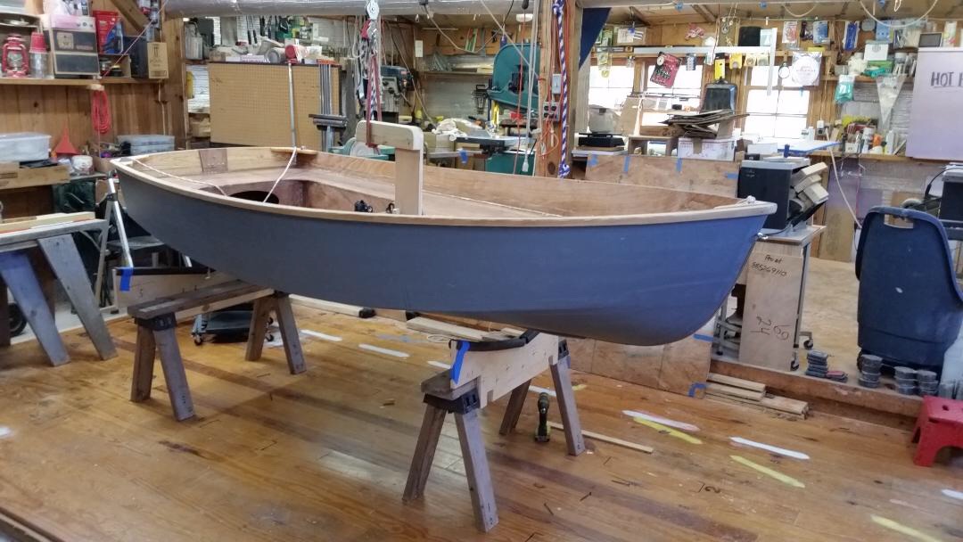
Thanks for the timely photos, Mark. I just flipped my S12 to start the keel. I like your clever "clamp/strap" hold downs.
-
Thanks Graham, great idea on the 3/8" round over bit for the legs. How about the gunwale inner where your back rests? Do you do a 3/8" there too?
-
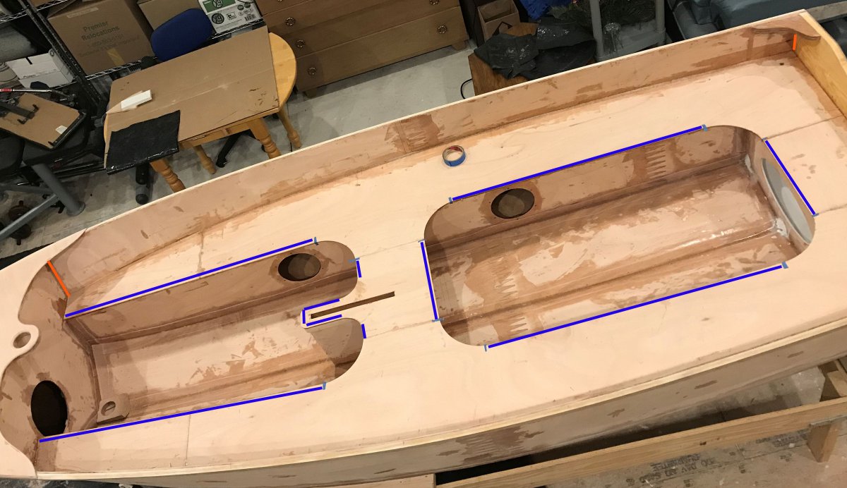
First question: In the photo below are some blue lines at the seat tops. Some of my seat top overhangs (the lateral ones) are up to 9mm of overhang. I was planning on making a router 1/4" radius on all the blue lines & then blending into those soft sweeping curves around the corners. Is there a reason to keep any of these overhangs? I suppose if I wanted to do a paint color change, a slight overhang would give me a clean paint line.
Second question: also in the photo, are 2 orange lines marking the vertical seams above the seats. Should these seams be glassed? What about the top of the seat where it joins with the front bulkhead the transom & the side hull? Any glass required on the bow deck to the gunwales?
Thanks.

-
On 7/30/2020 at 10:51 AM, J. Cote said:
Thank you Alan for all your help. This is great!
Now I have to ask.... What did you use for the floor non skid?
-
On 7/28/2020 at 8:43 PM, Alan Stewart said:
This is the foam that Randy and Bobbie used on their Spendthrift it's really nice stuff. I bought it for my trimaran and it worked great.
(disclosure note: this is an amazon affiliate link)
Thank you Alan for all your help. This is great!
-
17 hours ago, Alan Stewart said:
On the Spindrift 12 some have probably doubled up those radii but I am pretty sure I've only seen it shown in Graham's design on the CS-17 and 20 and I added it to the CS-15 kit as well. It does give the ability to put a larger round-over on those edges.
Alan, did you put the doubler on Randy's S12 next door? I'll guarantee that I tugged on that "handle" with all my might while trying desperately to get back in the boat. HA HA. I don't remember worrying about it giving way. I'm finding the coats of epoxy really add strength.
On another note, where did you find the grey seat pads on Randy's boat? It really helps make it a non slip surface.
-
Hi Alan,
You put these Seat Doubler Triangle blocks in for the seats unsupported radii on your CS15. Do you recommend them for the S12 as well?


B&B's latest and grandest launching.
in B & B Yachts Forum
Posted
My gosh, he is so alert! Love the first picture of Taylor holding him. Congratulations to you.